By Paul C. Frankenberger, P.E.; Matthew M. Merritt, P.E.; and Mark Myers, P.E. – The concept of secondary geogrid layers located at the face of a mechanically stabilized earth wall is similar to the use of secondary geogrid reinforcement in MSE reinforced slopes. In slopes, the secondary geogrid layers are used to stabilize the slope face between the primary geogrid layers. The result is closely spaced geogrid layers at the face of the slope. The long-term design strength (LTDS) of geogrid reinforcement is used in MSE design. The LTDS is determined by applying reduction factors to the geogrid ultimate tensile strength. Reduction factors account for creep resistance, chemical durability and installation damage. In allowable stress design of MSE walls, the LTDS is reduced by a factor of safety of 1.5.
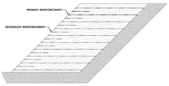
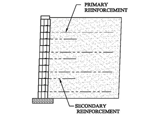
In MSE walls, secondary geogrid reinforcement layers can be used between primary geogrid reinforcement layers. Secondary geogrid layers are located at the face of the wall and do not extend for the entire length of the primary geogrid layers. (See Figures 1 and 2.) The secondary geogrid reinforcement is used to redistribute high facing connection loads that occur from seismic loading and high overburden loads over a larger number of geogrid layers. This redistribution reduces the connection demand of the primary geogrid layers.
There are multiple types of MSE wall facing, such as segmental retaining wall (SRW) units, precast concrete modular (PCM) units, welded wire baskets, and rockery boulders. Secondary reinforcement has been used in frictional connection MSE facing that rely upon a connection based on friction of a geogrid layer inserted between the MSE wall facing. Secondary geogrid has also been used where it is placed behind larger MSE wall facing, such as with PCM units, gabion wire baskets, and rockery boulders. In these cases, the secondary layers do not connect to the facing. Secondary reinforcement has generally not been used for MSE walls that rely upon a mechanical connection between geogrid reinforcement and MSE facing units. The reason is that MSE walls units which feature mechanical connections are generally designed to have sufficient connection capacity such that the geogrid design strength governs and not the connection capacity.
PODCAST: Composite Materials Are Changing the Conversation in Geosynthetics
SECONDARY GEOGRID REINFORCEMENT DESIGN APPROACH
A research study was conducted at the University of Kansas and sponsored by the Kansas DOT. The results of the study determined that secondary geogrid reinforcement reduces the load on the primary geogrid layers and the MSE wall face. This analysis can be calculated in common MSE wall software programs such as the National Concrete Masonry Association’s SRWall 4.0 and MSEW 3.0, which was developed by Adama Engineering, Inc. The SRWall analyses show that with the exception of connection capacity, primary geogrid layers satisfy the overall active wedge stability and are sufficient to satisfy external stability (sliding and overturning). Insertion of secondary geogrids can be used to reduce the connection capacity demand of primary geogrid layers. Secondary reinforcement can be analyzed in MSEW, which allows the input of secondary geogrid layers as intermediate reinforcements. A minimum embedment length of three feet is given as typical length of intermediate reinforcement to develop resistance to connection load. The program uses the shorter intermediate layers to carry the facing load exclusively in the connection capacity evaluation. The intermediate or secondary geogrid layers are not used in the evaluation of other failure modes which rely only upon the primary geogrid reinforcements.
MORE GEO: Start every week with the GeoWire
In software programs which are not set up for secondary reinforcement design (such as SRWall), the evaluation can be made by running two separate analyses, one with both primary and secondary reinforcement modeled as full-length layers and the other with the intended primary geogrid spacing. The primary geogrid can be shown to satisfy all failure modes but connection and the other analyses with primary and secondary reinforcement to satisfy all failure modes including connection. Additionally, a hand calculation can be performed to show that three feet is sufficient embedment to resist pullout of the secondary reinforcement.
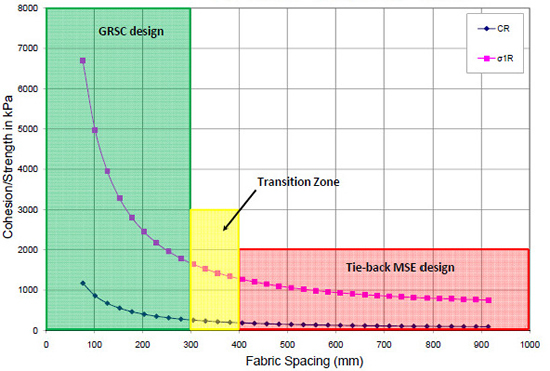
The use of a secondary geogrid can create a closely spaced geogrid structure similar to geotextile-wrapped temporary walls using wire forms to support the fabric-wrapped face. The concept of closely spaced geosynthetic layers in permanent MSE walls is used in the Federal Highway Administration (FHWA) Geosynthetic Reinforced Structure (GRS) system (Adams et al. 2011). Research conducted at the University of Colorado in Denver concluded that closer spacing results in an apparent cohesion at the MSE wall face, as shown in Figure 3 (VanBuskirk 2010). For soil in the reinforced zone, secondary geogrid layers result in locking in lateral stress from compactive effort, essentially arching the soil material between the geogrid layers. For shorter spacing, the arching effect is more pronounced, as indicated by the larger apparent cohesion shown in Figure 3. This technology was used in the design presented in the rockery case study described below.
PORTOLA SOUTH CASE STUDY: SRW UNITS MSE WALL
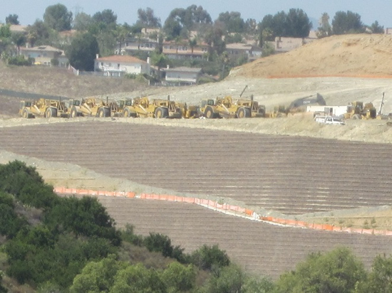
The Portola South project is a residential development located in Lake Forest, Orange County, California. The site is located within the foothills of the Santa Ana Mountains and has an elevation difference of 180 feet across the 93-acre site. Large fills were needed to level the site for residential building pads and segmental retaining walls were used to increase the usable area.
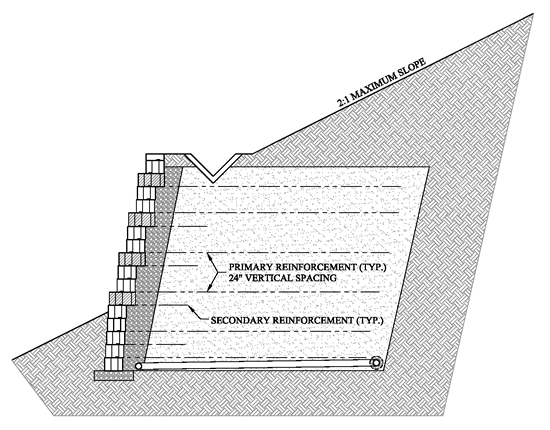
There were 21 SRWs totaling 173,000 square feet of wall area. The owner selected the SRW facing type based on multiple wall options, including color, batter, and plantability. The geogrid design required a manufacturer offering a wide range of structural geogrid strengths and a strong quality control and quality assurance program. Figure 4 shows a typical MSE wall section for the Portola South project.
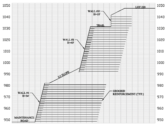
The tallest portions of fill on the site paralleled the western boundary and consisted of multiple tiered walls and 2:1 slopes. The fills were up 100 feet in height with the tiered walls up to 40 feet in height. The geogrids within the SRWs were designed to provide wall stability but were also increased in length and strength to resolve global stability issues. It was determined during the initial design phase that the friction connection capacity of the block and geogrid was controlling the design. That is, the loads at the face of the block were so high that the design required stronger and more frequently placed geogrid layers to satisfy connection capacity requirements than otherwise would be required for other failure modes. The loads at the face of the wall were greater than normal due to the large 2:1 slopes and additional tiered walls. Figure 5 shows a site section from the Portola South project emphasizing the significant overburden loads on the lowest tiered wall.
Southern California is notorious for its earthquakes and high seismic loads. This project is no different. The walls were designed for a horizontal ground acceleration coefficient (Kh) of 0.18g, which corresponded to one third of the peak ground acceleration (PGA) of 0.54g. The seismic design for connection strength was the controlling factor in the geogrid design.
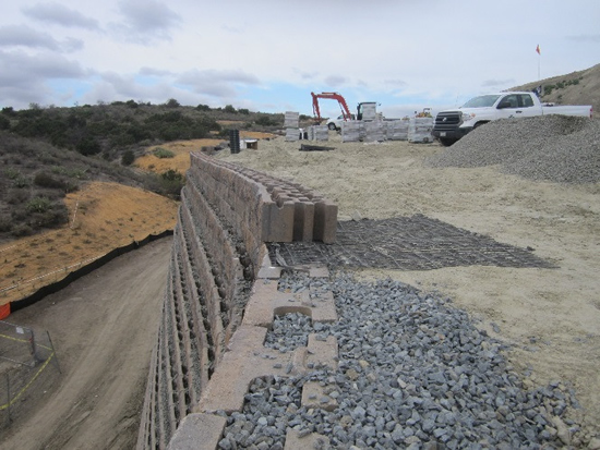
When using the primary geogrid reinforcement-only design, the total area of geogrid needed was so great it affected the economics and installation speed of the SRW. The design solution was to use 4-foot-long secondary geogrid reinforcement placed at the face of the wall between the primary geogrid reinforcement layers to distribute the loads at the face of wall and reduce the connection capacity needed on the primary reinforcement layers.
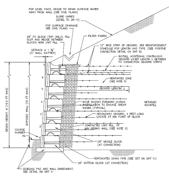
Figure 6 illustrates an MSE wall section with primary and secondary geogrid reinforcement.
The MSEW program was used for the design of the Portola South project according to FHWA design methodology (Berg et al. 2009). The MSEW program allows for the insertion of the secondary reinforcement to be used in the connection strength calculation while utilizing the primary geogrid for all other calculations.
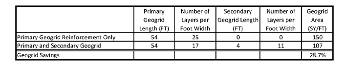
The tallest section of Wall No. 4 can be examined to compare the use of primary geogrid only versus primary and secondary to determine the geogrid savings. Table 1 shows the use of secondary reinforcement reduced the overall geogrid quantity by 28.7 percent while providing a structurally sound and economically feasible SRW system.
LAKE SHERWOOD PCM UNITS MSE WALL CASE STUDY
Lake Sherwood, California is an unincorporated community in the Santa Monica Mountains located within Ventura County. The 2013 – 2014 PCM unit retaining wall project consisted of the construction of eleven retaining walls which varied up to about 16 feet in exposed height. The walls were constructed to create a roadway and new lots within the luxury home development. PCM walls were selected for both their aesthetic rock face and for gravity wall applications at many locations. The configurations of the walls varied and included both cut and fill walls supporting both level and sloped conditions. PCM gravity walls typically worked to about 7.5 feet tall but required the use of larger 60-inch-deep concrete units. For walls in competent bedrock cuts even taller gravity walls were used. Static analyses of the retaining walls resulted in appropriate factors of safety.
The geotechnical report recommended a PGA of 0.47g and the USGS website 2008 seismic deaggregation reported a PGA of 0.34g to have a 10% chance of exceedance in 50 years. The SRWall design software utilized Mononobe Okabe (M-O) methodology as described in the NCMA design manual (NCMA, 2010). Known limitations of the M-O method include high ground acceleration and tall slopes above and below MSE walls. For these reasons, the seismic analyses were decoupled to address internal and external failure modes. External failures modes of the MSE structure were analyzed in a manner similar to a reinforced slope. The pseudostatic seismic global stability analyses were completed which included the geogrid reinforcement. California Geologic Survey (CGS) Special Publication 117A (Guidelines for Evaluating and Mitigating Seismic Hazards in California) was used to select the pseudostatic coefficient using Figure 1 on page 30 of the document. The CGS method determined a pseudostatic coefficient of 0.24 for an earthquake having a PGA of 0.47g PGA. Seismic internal stability calculations were then performed using the highest value of PGA recommended by AASHTO (2002) of 0.29g. Both CGS and AASHTO assume some displacement as the basis for reducing the PGA. The internal stability analyses resulted in some connection overstressing in seismic.
For the design, 4-foot-long secondary geogrid reinforcement was used to manually distribute the load from primary geogrid to both primary and secondary reinforcement. Figure 9 depicts a typical section for 28-inch-deep PCM units supporting fill. It should be noted that the design did incorporate positive connection PCM units to add additional resistance against toppling of the uppermost units in an earthquake. Use of secondary geogrid reinforcement resulted in cost savings and increased manufacturing efficiency compared to using standard 28-inch-deep PCM units. The use of secondary geogrid reinforcement allowed the manufacturer to meet the production efficiency needs of the project.
SAN JOSE ROCKERY MSE WALL CASE STUDY
For a new subdivision in San Jose, California, rockery retaining walls were selected and approved by the City based upon their aesthetic appeal. The rockery walls were designed using the methods described in the FHWA’s 2006 Federal Highway Lands manual, “Rockery Design and Construction Guidelines.” At one location, a rockery wall was to be constructed below an MSE slope. For design, it was assumed that construction of the MSE would occur first followed by excavation for the rockery wall and construction of the rockery.
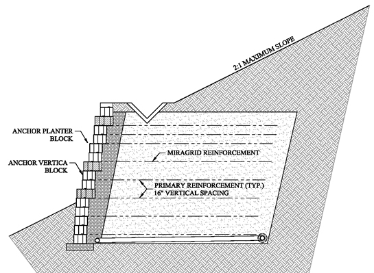
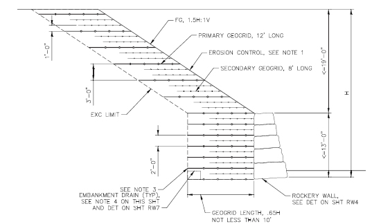
The geogrid layout for the slope consisted of primary and secondary reinforcement. Shoring for construction of the rockery was designed as geogrid reinforcement for an MSE retaining wall. As noted earlier, the tight geogrid reinforcement functions like an apparent cohesion to provide a stable excavation with a near vertical cut. The geogrid layout for the slope and rockery is shown in Figure 10. The final design of the rockery assumed a flatter slope in design than the actual conditions to account for the benefit of the MSE and geogrid reinforced slope. For this project, the primary and secondary geogrid reinforcement provide an MSE structure which is then faced by the rockery wall instead of precast MSE wall units. There is no connection of the geogrid reinforcement to the rockery face. In this design, the primary and secondary reinforcement are the MSE facing which is then protected against weathering and erosion by the rockery wall. The entire reinforced earth structure was also evaluated using global stability analyses.
THE TAKEAWAY
Secondary geogrid reinforcement can be used in the evaluation of MSE walls to reduce cost and improve the performance of wall facing. In conditions of high seismic loading and overburden loading, MSE wall facing connection strength commonly controls the design, resulting in closely spaced primary geogrid reinforcement layers. The use of shorter secondary geogrid layers placed between primary geogrid layers can result in a more efficient and cost effective design.
Paul C. Frankenberger, P.E. was with TenCate Geosynthetics when this article was originally published. He has since changed companies. Matthew M. Merritt, P.E. is with Red One Engineering, Inc. Mark Myers, P.E., G.E., is with Cal Engineering & Geology, Inc.
ADDITIONAL REFERENCES
(NOT LINKED TO IN ARTICLE)
Berg, R.R., Christopher, B.R. and Samtani, N.C. (2009). Design and Construction of Mechanically Stabilized Earth Walls and Reinforced Slopes – Volume I, FHWA NHI-10-024, National Highway Institute, Federal Highway Administration, U.S. Department of Transportation, Washington D.C. USA.
NCMA, 2010, Design Manual for Segmental Retaining Walls, 3rd edition, 13750 Sunrise Valley Drive, Herndon, VA 20171.
VanBuskirk, C. (2010). Adoption and Implementation of GRS Design Concepts A Consultants Perspective, available from GCS Wall website.


