
The following is an excerpt from “Sustainable Use of Geosynthetics in Dykes” by Pietro Rimoldi, Jonathan Shamrock, Jacek Kawalec, and Nathalie Touze. Their article was first published in the MDPI journal Sustainability, 2021, 13(8), 4445, ©2021 by the authors. This article is an open access article distributed under the terms and conditions of the Creative Commons Attribution (CC BY) license.
View the full, original journal publication
The article, which has been authored by some of the leading geosynthetic practitioners and researchers in the world, is a notable contribution to sustainability discussions and to the growing movement of open access publishing. Sustainability and openness are also two leading initiatives of the International Geosynthetics Society (IGS). See the IGS’s new Sustainability page for recommendations and access to an ever-growing list of resources surrounding geosynthetics and sustainability.
The follow excerpt for “Sustainable Use of Geosynthetics in Dykes” is from Section 4, Applications of Geosynthetics in River Dykes; Subsection 4.3, Geosynthetics for Reinforcement. The figure references are as they are in the full article. References are noted at the end.
GEOSYNTHETICS FOR REINFORCEMENT IN RIVER DYKES
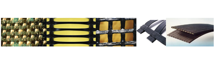
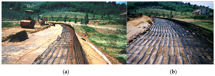
Geosynthetics can be used for increasing the stability of a dyke, or increasing its slope angles and thus reducing its footprint, by building reinforced fill structures. Engineering design procedures and construction methods are well established for these geosynthetic reinforcement applications. Reinforced fill is comprised of three basic components: fill, geosynthetic reinforcement and facing. The fill is usually a relatively clean granular soil material. The reinforcement is usually laid in horizontal layers. The facing is connected to the reinforcement and retains the face of the fill; it is usually made up of precast concrete elements, or by wrapping-around the geosynthetic reinforcement. Geogrids, woven/knitted geotextiles, and geostrips (Figure 11) are typically used for reinforcement in dyke construction.
The selection of the type of reinforcement and its specifications are undertaken based on design, as the reinforced soil body behaves similar to a structural element, on which the stability of the dyke ultimately depends.
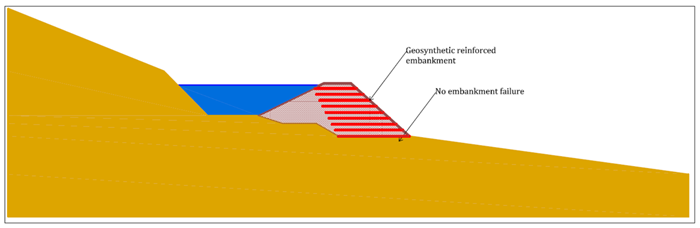
Geosynthetic reinforcement can be incorporated at the base of embankments to aid in construction, reduce potential for foundation failure and excessive deformation, facilitate embankment construction on sloping ground, and to construct steeper embankment slopes.
RELATED: Flood Protection – Rehabilitation of a Dike in Germany
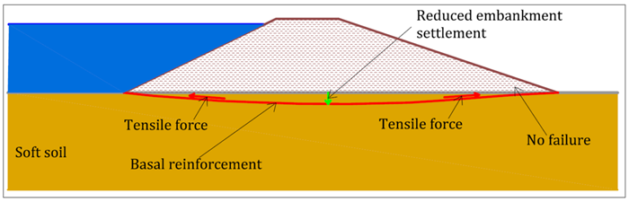
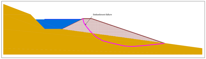
Dykes frequently must be constructed across soft and compressible soil, with the potential for embankment failures (Figure 12). Basal geosynthetic reinforcement placed at the bottom of the embankment improves stability and may reduce the required width of the embankment (Figure 13), thereby reducing foundation preparation and embankment soil volumes.


While geosynthetic reinforcements placed across the dyke can afford the stability of each cross-section, additional reinforcement placed along the dyke axis can minimize the length effect, as shown in Figure 18. This longitudinal reinforcement can be installed during major refurbishment works on an existing dyke, and can be included in the original design for new dyke construction. The cost of the longitudinal reinforcement is negligible compared to the savings of avoiding potential dyke breaks due to the length effect, and consequent costs.

View the full, original journal publication
REFERENCES
21. Design and Construction of Levees, Manual No. 1110-2-1913; Department of the Army, U.S. Army Corps of Engineers: Washington, DC, USA, 2000. [USACE – PDF]
22. Blond, E.; Boyle, S.; Ferrara, M.; Herlin, B.; Plusquellec, H.; Rimoldi, P.; Stark, T. Applications of Geosynthetics to Irrigation, Drainage and Agriculture. Irrigation and Drainage; John Wiley and Sons Ltd.: Hoboken, NJ, USA, 2018. [Google Scholar]
THE AUTHORS
Pietro Rimoldi is a geosynthetic consultant based in Milano, Italy. Jonathan Shamrock is with Tonkin & Taylor Ltd. in Auckland, New Zealand. Jacek Kawalec is with the Department of Geotechnics & Roads, Faculty of Civil Engineering, Silesian University of Technology in Poland. Nathalie Touze is with SDAR, Université Paris-Saclay INRAE in France. The authors retain copyright to this open access publication.


