Electrical integrity/leak location surveys were made on lining system components during the construction of two railroad locomotive fueling platforms. From the top down one of the lining systems was as follows:
- 12 in. stone cover
- Geotextile/geonet/geotextile composite (geocomposite)
- Primary textured geomembrane GCL Geocomposite
- Secondary textured geomembrane GCL Tertiary textured geomembrane Geotextile (cushion)
- Prepared stone subgrade
Surveys (a combination of wading, water lance, and soil-covered techniques) were made on each geomembrane (with four sumps) and on the primary geomembrane with stone cover. We found
- the lack of uniform wetting of the cushion geotextile affected the reliability of the tertiary liner survey
- it was beneficial to lightly irrigate the GCLs before placing the overlying geomembrane
- the exposed edge of a GCL can dry out such that it has inadequate conductivity for the attachment of a current return electrode
- it was essential to thoroughly wet the geocomposite over the primary geomembrane for an effective survey. Leaks at extrusion welds, and at a knife cut, were found in, and very close to, sumps.
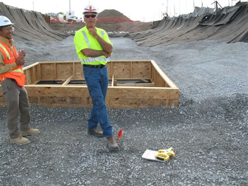 |
| Tung Vu (URS Seattle, CQA) and Phil Brennan (TKDA St. Paul, Construction Manager) at flagged location of liner leak indication signal. |
The primary geomembrane is underlain by a GCL and is covered by geocomposite and a 12 in. stone layer. The GCL had been lightly irrigated before covering to maximize the upper geotextile’s electrical conductivity for a geoelectric integrity survey.
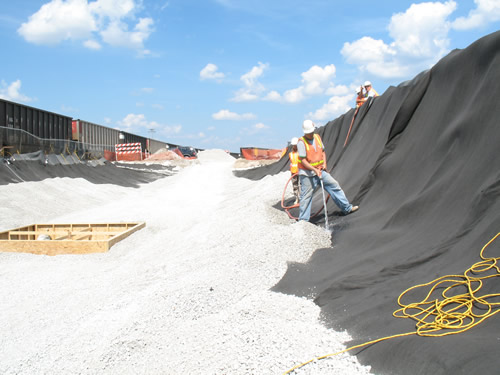 |
The geocomposite was also thoroughly wetted (photo) prior to the integrity survey to assure its electrical conductivity. The leak was a 0.5 in. knife cut made when the geocomposite was cut on top of the liner.


