 |
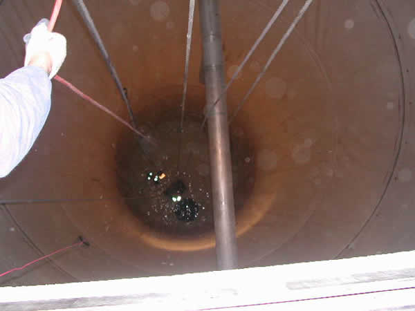
| The figure shows a view down the single PVC geomembrane lined concrete silo which is 21 ft in diameter lined to a height of 65 ft. |
There are three double-capped batten strips attaching the liner and cushion/drainage geotextile to the walls at different heights. There is a 10 in. diameter outlet pipe in the floor to one side – the black circle in the floor is the pipe boot. The plastic-lined outlet pipe is flanged to a stainless steel pipe under the silo floor. Thus the outlet pipe appears as a large leak consuming much current that would otherwise be used to locate the small liner leaks of interest. Both applied electric potential and acoustic survey techniques were used to locate suspected leaks.
The current return (ground)electrode on the underside/outside of the liner was attached to several different metallic features on/in the silo concrete, but the best location was found to be the stainless steel inlet pipe (top to bottom of the figure) that is supported by a stainless steel plate bolted to the inside concrete wall above the top of the liner.
The survey was attacked in several stages:
With the water level about 3 ft above the upper batten strip the strip was surveyed with a handheld scissor (adjustable) probe from a small inflatable boat. Each vertical seam (5 ft apart) was then surveyed from top to bottom using a remote linear probe lowered and raised against the liner. The signal from the outlet pipe was noticeable below about 25 ft from the floor. This signal was significantly stronger on the side closer to which the pipe was located.
A small leak along the edge of the batten cap strip where a small patch had been placed over the edge was found. This is a very common leak location. A 3/8 in. vertical linear cut/puncture was found about 23 ft from the floor. With the water level lowered to a depth of about 3 ft a wading survey with the handheld probe was found, as expected, to be impossible due to the large signal generated by the outlet pipe and due to the closeness of the current injection electrode. However, an acoustic survey using a sensitive microphone was able to locate a leak in the floor/pipe boot corner weld. The boot was on the inside of the pipe.
An inflatable rubber plug was placed in the outlet pipe which enabled an electrical survey to be performed. A leak through a scratch under the edge of a small patch was found, as was a 0.08 in. linear puncture in the floor.
With the same 3 ft of water on the floor, and the plug in place, a water lance survey was performed on the wall liner to a height of about 25 ft.
For maximum sensitivity this survey required careful placement of applied potential electrodes, careful integration of different types of survey probes, and careful integration of electrical and acoustic techniques. Even though it was white the liner required very thorough cleaning and just-the-right-angle light to find the 80 mil long flaw in the floor. Even knowing it was there it still took a little while to relocate. Very often indicated leaks are overlooked due to the lack of a proper close inspection.
For more information on this and other leak location projects, please contact Ian Peggs, at I-CORP INTERNATIONAL.


