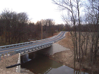
GRS bridge abutments have been typically produced savings of more than 25% versus traditional designs and are much faster to construct. Here in Part 1 of 2, Gordon Keller discusses the development and benefits of the GRS bridge abutment approach. In Part 2, he focuses on case studies.
**

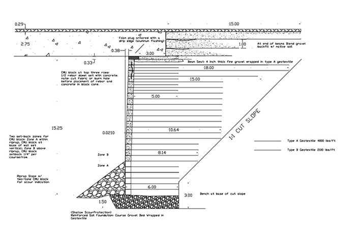
Geosynthetic-Reinforced Soil (GRS) systems for bridge abutments and piers have received increased attention and interest today because of their ease and speed of construction and relatively low cost. GRS abutments can offer a relatively inexpensive and practical solution for bridge foundations in a wide range of applications including low volume roads, highways, and trails. This technology has been used on many bridge projects over the past decade, both in the US and worldwide. It is currently being used by many American counties in replacement of aging bridges and can be applied to a wide range of foundation conditions ranging from bedrock to a very soft foundation material.This adaptation of reinforced soil technology to bridge structures and their approach fills offers an excellent opportunity to simplify construction, reduce construction time, and reduce cost on structures where this technology is appropriate. In this design concept the actual bridge superstructure rests upon the GRS abutment wall, thus minimizing differential settlement and eliminating the problematic “bridge bump” found on many structures. The technology has been adapted to both trail and road bridges.Some of the first GRS bridge abutments used on forest roads were constructed in Alaska almost 20 years ago; they are still performing well today. A GRS, timber-faced bridge abutment was also constructed on a trail bridge in Northern California in 1999 because of cost and the remote location of the bridge. The Mammoth bridges, in the mountains of Northern California, with high design snow loads and high seismic accelerations, afforded an opportunity to design, construct, and monitor GRS abutments under difficult service conditions. Performance to date has been excellent.Today many GRS bridge abutments are being used by counties such as Defiance County, Ohio while replacing their old structures. Typical cost savings of more than 25% are being realized compared to conventional bridge abutments, and the construction is faster.Particular installation examples, such as the Alaskan and Northern California projects noted here, are described in greater detail in Part 2.The soil mass of the abutment system is constructed like a reinforced soil or mechanically stabilized earth (MSE) retaining structure, using reinforcing layers of a polymeric geosynthetic material such as geotextiles or geogrids. Reinforced soil backfill material used has typically been a crushed aggregate or granular soil to facilitate ease of construction and minimize total structure settlement. Various “flexible” facing materials have been used, including timbers, modular concrete blocks, or rigid facing material such as concrete, depending on the design and site conditions.Principal advantages of GRS bridge abutments include:
- The design can be more forgiving to differential foundation settlement and can eliminate the infamous “bridge bump” caused by differential settlement between the abutment foundation and the approach fill
- GRS structures can be constructed relatively quickly and can be built by maintenance personnel
- A GRS structure (wall) is relatively easy to construct, and it does not require specialized drilling equipment often used in pile or caisson foundations
- GRS structures are likely more economical than conventional concrete or pile foundation structures
- GRS abutments constructed with backfill and geosynthetics are ideal for temporary piers and emergency work because of their ease to construct and relative ease to remove or demolish
Disadvantages of GRS bridge abutments include:
- The long-term durability of the facing material must be considered
- A non-rigid GRS wall can be susceptible to stream scour and abrasion
- The entire structure could have potentially high total settlement if the GRS abutment is placed upon a very soft, deep foundation
The design of GRS soil bridge abutments combines many of the elements of conventional bridge design and typical mechanically stabilized earth, or GRS retaining wall design. Several design issues are unique to this combined structure. The key design elements include the bridge dead load and live loads, as well as snow load and seismic loads where applicable; the reinforcement type, and its corresponding tensile strength; the reinforcing material spacing, typically ranges from 15 to 60 cm (6 to 24 inches); length of the reinforcement, usually estimated at 0.7–0.8 times the wall height; the facing elements, usually concrete blocks or timbers, and connection details; scour considerations and abrasion resistance; and foundation requirements.The recent Federal Highway Administration publication “Geosynthetic Reinforced Soil Integrated Bridge System Synthesis Report” thoroughly documents the current design methodology used for this GRS technology. It is available on-line at:http://www.fhwa.dot.gov/publications/research/infrastructure/structures/11027/index.cfmFor case studies, see Part 2 of this article.Gordon Keller, P.E., has worked since 1972 for the US Forest Service and has played a key role in numerous international training courses, engineering evaluation missions, and conferences. He’s co-led workshops in the Sudan, conducted rural road and environmental analysis throughout Latin America, and worked with the World Bank, the Pan-American Highway Institute, the Rainforest Alliance, and many other organizations. He has also worked closely with the International Road Federation (IRF), a non-governmental, not-for-profit organization dedicated to promoting the development and maintenance of better, safer and more sustainable roads and road networks.
 |


