Electrically assessing the integrity of systems that incorporate geomembranes – 23 considerations that will improve your designs and facilities
State regulators are increasingly requiring the periodic (circa 5 years) assessment of the integrity of secondary containment systems around large fuel oil storage tanks. This can be done very quickly using electrical methods if the lining system is correctly designed. Do not even think about flooding the system with water to perform a hydrotest – they are notoriously inaccurate and take too long (>10 days). And if you think there is a leak you still have to locate it. Applied potential methods immediately locate leaks as small as 1 mm in real time and can cover an area of about 1 ha (2 acres) in one day.
 |
Here are few pointers on designing, or determining whether an applied potential survey can be performed on, a secondary containment lining system:
1. If exposures to fuel are only short term (a few days) a high-density polyethylene HDPE) geomembrane may be adequate.
2. If exposures may be long there are more resistant geomembrane materials, such as alloys of polyvinyl chloride (PVC) and ketone ethylene ester (KEE).
3. Double lining systems are overkill for this application.
4. The geomembrane may be able to be used exposed.
5. If exposed there should be a sump around the drain, or the drain opening should be a little higher than the liner.
6. If HDPE is exposed, ensure it is an HDPE with good thermal aging, UV resistance, and stress cracking resistances.
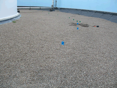
7. If not exposed, there must be an electrically conductive medium directly over the liner (often gravel/water).
8. There must be a conductive medium through the leaks being sought.
9. There must be an electrically conductive medium directly under the geomembrane.
10. The conductive media above and below the liner must not be in electrical contact other than through the leaks being sought.
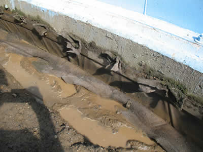
11. The geomembrane can be fastened to tank ring walls with batten strips or welded to cast-in studded HDPE strips.
 |
12. The same systems can be used to fasten to outer dike concrete ring walls.
13. Or anchor in trenches in the top of soil berms.
14. Cover soil on berm side slopes must be isolated from the subgrade soil at crests of slopes.
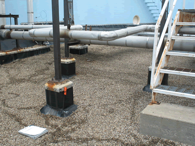
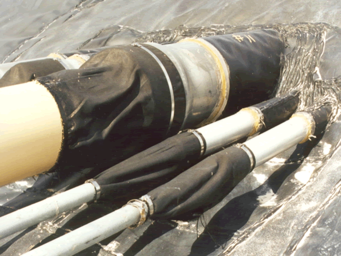
15. Minimize the number of pipe penetrations.
16. If you must have penetrations do not put them all together.
17. The drain should be a plastic pipe with opening a little above the soil cover.
18. Place liner boots around all penetrations so that battens/clamps are above the opening of the drain pipe.
19. Boots/clamps should also be above typical rainwater accumulation levels.
20. Do not cover battens or fastenings with cover soil (the soil must not contact ground).
21. If a geotextile cushion is used under the cover soil layer, it should not be fastened to the batten strips or above.
22. Ensure all grounding cables and connections from tank to ground are insulated from cover soil if they pass through the soil cover.
23. The geomembrane should be fully supported – wall/floor corners should be beveled.
 |
The basics one more time:
* Conductive medium above the liner
* Conductive medium through the holes
* Conductive medium below the liner
* Media above and below the liner not connected other than through the holes you are seeking
I-CORP will be pleased to review your plans and drawings for survey-ability.
One final reminder: do not compete to see how many penetrations you can get through the berm in one location! This photo exemplifies a design type that lacks geomembrane understanding:
 |
Ian D. Peggs, Ph.D., P.E., P.Eng., is president of I-CORP INTERNATIONAL Inc. He can be reached at icorp@geosynthetic.com.


