In this two-part article, Alain Hérault, Sabihi Abdelhak, and Chakib El Iraki write on the new French standard NF P 94-270 and how it establishes design rules for the use of geosynthetics and other reinforcing materials in reinforced earth walls and steep slope applications. These rules, based on the partial factors defined in Eurocode 7 (EN 1997), were applied to a huge Mediterranean bypass project in Morocco to determine tensile strengths, lengths and spacing of geogrids. In Part 2, the authors address design, installation procedures, and quality management.
 |
The construction of the road link between Tétouan and Al Hoceima, Phase 2 of the Mediterranean bypass road project linking Tanger to Saida, forms an integral part of the Northern region development policy that the Moroccan government has defined as a priority objective. The primary goals that the completion of the bypass will deliver are threefold:
- Opening up of the northern Mediterranean coast, while improving the infrastructure of the region and the access of the population to the region
- Development of the region’s economic potential, particularly tourism and maritime activities. This is a key component of any development project
- Improvement of the administrative system, especially in its supervisory role in the region
The Rif region shows the highest level of seismicity in Morocco and experiences the largest number of earthquakes in the country. Historically, four earthquakes from 1910 to 1926 caused substantial damage to Melilla. However, the most severe earthquake, with a magnitude of 6.2 on the Richter scale, occurred in northern Morocco on 21 January 1909 in the Tétouan region. Seismicity is considered to be one of the major causes of the phenomenon of instability. It is a disturbing factor in the equilibrium and stability of embankments, slopes and mountainsides, demanding the selection of highly flexible support techniques able to withstand earthquakes; hence the use of earth walls reinforced with geogrids.
Earth Walls Reinforced with Geogrid
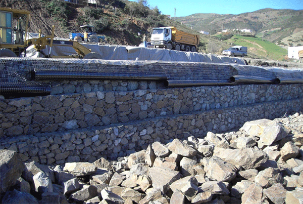
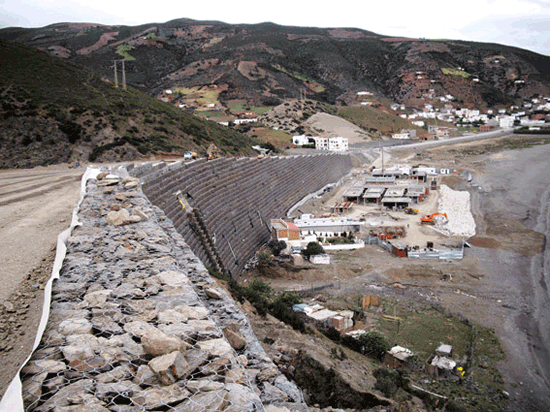
There are 35 of these in Phase 2, with a maximum wall height of 31 m between kilometer points 4+370 and 4+750. They will require the installation of 1.5 million m2 of reinforcing geogrids. All facings are inclined at 63° (1H/2V) and consist of 1 m x 1 m x 1 m gabions filled on site (Photo 1). ASQUAL-certified drainage geocomposites ensure the drainage of the excavated embankments behind the walls.
 |
THE EUROCODE REGULATORY FRAMEWORK
The geotechnical calculation of structures has been standardized by Eurocode 7 since 2010, the end of the transitional period of coexistence with national standards fixed by the European Commission. To ensure that reinforced earth structures are designed in accordance with this requirement, the French Commission for Standardization of Geotechnical Structures (CNJOG) drafted the NF P 94-270 standard published by AFNOR in July 2009. This new standard applies the principles of limit state calculation with partial factors as defined in Eurocode 0 (EN 1990/A1) and Eurocode 7 (NF EN 1997-1) and related to the calculation of the reinforcing element in earth reinforced structures, notably to geosynthetics.
Eurocodes establish a semi-probabilistic approach to safety; for example, the effects of loads are now determined through combinations of different loads in permanent or temporary project scenarios or in accident-related or seismic project scenarios. For example, the partial factors listed in Table 1 apply to sustainable or temporary project scenarios for checks of internal and external stability. The partial factor to be applied depends on the type of load (permanent or variable) and its favorable or unfavorable effect on stability. Accordingly the permanent load (γGinf = 1.0) on a structure will not be increased and the variable load will not be considered (γQinf = 0) while checking the sliding of the structure, since both variables improve the structure’s resistance to sliding. On the contrary, if they are located at the back of the structure, these loads will be increased by a coefficient γGsup = 1.35 for the permanent load and a coefficient γQsup = 1.50 for live loads since they then reduce the stability of the structure against sliding.
 |
The long-term design strength Rt;d is calculated from the ultimate tensile strength (95% confidence limit) Rt;k of the reinforcing product, as measured in a laboratory in accordance with EN ISO standard 10319, using equation 1:
 |
ρ :Partial factors regarding geosynthetic tensile strength, based on tests carried out in accordance with ISO/TR 20432.
ρflu : Creep behavior
ρend : Installation damage
ρdeg : Durability
γM;t is the partial material factor on tensile strength for all reinforcing products = 1.25.
In case specific test results are not available, default values are given in the NF P 94-270 standard. These lead to ρ values ranging from 5 to 12 under normal installation conditions.
Creep Behavior
The creep behavior of a geosynthetic under constant load must be examined according to two criteria:
- Its ability to resist a given tensile load for the entire service life of the structure
- The elongation of the product between its commissioning, conventionally fixed at 10 hours after initial tensioning, and the end of service life of the structure, generally fixed at 100 years (postconstruction period).
These two criteria lead to the determination of two partial factors; the more unfavorable of the two determines the allowable stress level in relation to the creep behavior.
Enkagrid® PRO geogrid, selected for the Mediterranean bypass, has proven to offer a very high level of allowable stress; this exceeds 68% for a service life of 120 years and a post-construction elongation limited to 1%.
Installation Damage and Durability
This partial factor depends on the mechanical aggressiveness of the fill material used, the compaction energy (medium, high) and the type of reinforcing geosynthetic, notably the size of its components. A product consisting of straps of high modulus extruded polyester (PET) polymer has proven to be much more resistant than other products consisting of filaments. The in-situ damage testing performed in France has shown that the geogrid chosen for the Mediterranean bypass project, which comprises laser welded extruded polyester straps, suffered no loss of strength under typical conditions considered to be “very severe” according to the NF P 94-270 standard.
Hydrolysis is considered to be the main chemical degradation process of PET. In an environment where the pH is generally between 4 and 9 the internal hydrolysis process will degrade the polymer chains over time to a certain extent.
The hydrolysis resistance of the geogrid concerned was investigated by BAM – Bundesanstalt für Materialforschung und -prüfung – in a pH-neutral environment using a complex test procedure developed to address the following topics:
- Hydrolysis resistance at different temperatures
- Hydrolysis resistance under stress
- Hydrolysis and tension crack resistance
In Part 2, the authors address design, installation procedures, and quality management.
Alain Hérault is a Product Manager with Bonar Geosynthetics, France; Sabihi Abdelhak is a Quality Manager for Arab Contractors-Houar-Elhajji-Lrn-Seprob; and Chakib El Iraki is the Public Works and Environment Department Manager for Valtech.


