
By Allan J. Breitenbach, P.E., and Chris Athanassopoulos, P.E. – Geosynthetic composite liner systems, consisting of geosynthetic clay liners (GCLs) underlying geomembrane liners, are seeing increased use in heap leach pads due to faster construction time and improved liquid containment compared to compacted clay liners. The improved hydraulic performance provided by geomembrane/GCL composite lining systems is well documented (Bonaparte et al, 2002). However, there is a concern by engineers and regulators over the stability of such composite liner systems, due to the low shear strength of unreinforced hydrated bentonite clay. Although Koerner (2012) and Fox and Ross (2011) report that there are no known cases of internal shear failure of needle-punched reinforced GCLs in the field, laboratory testing has shown that GCLs can experience internal failure at very high normal stresses, corresponding to low residual shear strength.
This article focuses on solving the liner engineer’s long-term slope stability challenge (or nightmare): high fill loads constructed on geosynthetic liner systems with potentially low-strength interfaces.
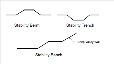
A summary of design and construction stabilization methods is presented to improve the long-term stability of worst-case composite liner strengths on planar surfaces. In particular, the focus will be on the non-planar features shown in Figure 1: stability berms, stability trenches, and stability benches. The concept is similar for all three cases: by introducing non-planar features to a planar surface, the resistance to sliding is greatly increased, resulting in improved strength and stability.

Breitenbach and Athanassopoulos (2013) presented a series of slope stability calculations for the hypothetical ore heaps shown in Figures 2 and 4. In both examples, the heap leach pad liner was assumed to have a low-strength unreinforced hydrated bentonite to geomembrane interface (equivalent friction angle = 7°, to simplify the low strength variations in friction angle and cohesion).
In the first example study section (Figure 2), several stability berms (also known as “speed bumps”) were placed along the toe of the structure to increase resistance to sliding.
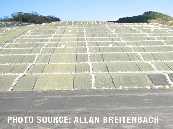
A photograph showing typical stability berms is presented in Figure 3.

Typical berm dimensions are 0.5 m high and 3 m wide, with berms spaced 5 m apart. The calculations showed that the addition of several stability berms along a critical portion of the heap leach pad liner dramatically improved the factor of safety (FS) against sliding, from a clearly undesirable FS = 0.9 to a favorable FS = 1.4.
In the second example study section (Figure 4), several stability benches (also known as “stair step benches”) were placed along the steep valley wall of the structure to increase resistance along the liner system. A photograph showing typical stability benches is presented in Figure 5. In this scenario, the FS was improved from an initial FS = 0.8 to FS = 1.3.

These findings have important design implications for leach pad liner systems with low interface strengths. The incorporation of non-planar features in liner systems containing GCLs can improve overall stability and maintain an adequate FS, even in worst-case loss of GCL internal strength due to rupture, pullout, or degradation of the needle-punched reinforcing fibers.
It is important to note that these non-planar stabilization techniques are not limited to just heap leach pads; they can similarly be applied to lined dams and landfill structures as well. The non-planar liner designs can turn the liner engineer’s worst nightmares into his best dreams for liquid containment and stability.
REFERENCES
Bonaparte, R., Daniel, D., and Koerner, R. (2002). Assessment and Recommendations for Improving the Performance of Waste Containment Systems. CR-821448-01-0, Environmental Protection Agency, Washington, DC, 1039 pp.
Breitenbach, A.J. and Athanassopoulos, C. (2013) Improving the Stability of High Fill Load Structures Built on Low-Strength Geosynthetic Interfaces. Conference Proceedings: Geosynthetics 2013, Long Beach, California, USA.
Fox, P.J. and Ross, J.D. (2011), “Relationship between NP GCL Internal and HDPE GMX/NP GCL Interface Shear Strengths”, J. Geotech. Geoenviron. Eng., 137 (8), 743–753.
Koerner (2012), “Selected Topics on Geosynthetic Clay Liners”, Keynote lecture at GCL University, Washington, D.C., April 12, 2012.
ABOUT THE AUTHORS
Allan J. Breitenbach, P.E., is with Ausenco, allan.breitenbach@ausenco.com. Chris Athanassopoulos, P.E., works for CETCO, catha@cetco.com.
NOTE: Allan Breitenbach will be a co-presenter for a short course on “Static and Seismic Stability for Heap Leach Pads” at Heap Leach Solutions 2013 (22-25 September 2013, Vancouver, Canada). He is also a co-author on the paper “Lessons learned in 30 years of laboratory liner interface strength tests compared to real world heap leach pad strengths.” Chris Athanassopoulos will present on “Design considerations for geosynthetic clay liners in heap leach pad liner systems.”
Improving the Stability of Heap Leach Pads


Latest Articles

Podcast: Ryan Kamp on Career Paths and Coal Ash
The latest episode of Geosynthetica's GeoTalk Podcast finds Tamara Tuttle (Atlas International Consulting) interviewing Ryan Kamp, President of Chesapeake Containment Systems, one of the...


