By Pietro Rimoldi, A.D. Gharpure, and R.R. Mahajan – Reinforced soil walls offer economic advantages over conventional mass gravity wall systems as the height of the wall increases. The cost of reinforcement constitutes an important part of the total cost of a reinforced soil retaining wall and can be as great as about 25% of the cost of the wall, depending on the wall height, backfill type, and design loading conditions.
It is possible to reduce the total cost of a reinforced soil wall by optimizing the vertical spacing of reinforcing geosynthetic elements, while ensuring the required Factor of Safety for the whole structure.
The reinforcement load in reinforced soil walls is commonly calculated from classic active earth pressure theory using the so-called contributory area approach. In this approach, the lateral earth pressure distribution from Rankine or Coulomb earth pressure theory is integrated over a distance equal to the spacing between reinforcement layers and the resultant load is assigned to the target reinforcement layer. In a tall retaining wall, the reinforcement load can vary with depth over a wide range of values. In such a case, more than one reinforcement type or spacing pattern along the wall height may be desirable.
Generally speaking, reinforcing geosynthetic elements with 200 kN/m ultimate tensile strength cost less than twice of a reinforcing geosynthetic with 100 kN/m ultimate tensile strength: hence a solution with half number of double-strength reinforcing layers will cost less than a solution with a double number of half-strength reinforcing layers.
International research and state-of-the-art practice have demonstrated that the former solution, if properly designed, ensures the same or even higher Factors of Safety than the latter solution. In particular, very tall geogrid reinforced soil walls have been built with 2 – 3 m vertical spacing between the primary reinforcing layers, even in very highly seismic areas, with excellent results both in terms of total costs and structural safety.
HYBRID REINFORCED SOIL STRUCTURES
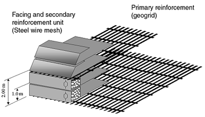
For building MSE structures it is possible to combine gabion units and wrap-around facing units (made up of double twisted wire mesh) with geogrids, considering in this case the geogrids as “primary reinforcement” and the “integrated tail” of the facing units as a secondary reinforcement (Figure 1). In these “hybrid” structures the primary reinforcement is used to provide the tensile forces required to ensure global stability with the desired Factor of Safety; while the facing units, which are produced with a “integrated tail” of double twisted wire mesh as a secondary reinforcement, provide the local stability at the face, ensuring that no local mechanism of direct sliding, pullout or rotational failure can occur. The primary reinforcing geogrids are always vertically spaced as a multiple of the height of the facing units.
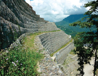
Very tall hybrid structures have been built all over the world according to this approach; the reinforced soil hybrid structure under construction in Sikkim (India), here presented, is over 80 m high and it has recently withstood an earthquake with a 6.9 magnitude with no visible damage.
Hybrid structures usually include a vertical spacing of reinforcement that is typically multiple of 0.74 m (29 inches) – 1.00 meter (40 inches), i.e., multiple of the height of a wrap-around unit or of a gabion unit.
However, in USA, the FHWA and AASHTO limit the vertical spacing of the reinforcement to 0.80 m (32 inches). Such requirements have also affected international MSE practice as many countries follow the USA guidance. Research and state-of-the-art practice here presented suggest that these limits have no real meanings and should be removed, at least for the hybrid reinforced soil structures here described.
Hybrid MSE structures are the most detailed and complete reinforced soil system present on the market, with the possibility of using either just the double twist wire mesh reinforcement or of combining it with facing elements of high-strength polyester geogrids in the case of very high works which are subject to large loads. The numerous possibilities for construction of the outer face enables the best choices to be made in every situation both from a technical-environmental point of view and in consideration of the landscaping requirements.
For the selection of the most suitable solution, the fundamental aspects for the correct design of MSE hybrid structures with geogrid primary reinforcement shall be carefully considered: in order to carry out a structural analysis of such structures it is required to check a large number of load conditions and geometries in accordance with the most typical and frequent situations which occur in walls and slope stability analyses.
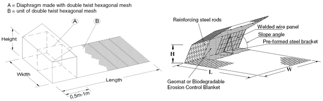
Hybrid structures rely upon the steel mesh and the geogrids placed horizontally within the slope or wall, with backfill compacted upon them. The gabion or wrap-around facing (Figure 2) is fully integrated with the steel mesh reinforcement, which works based on the friction acting along the surface of the wire and, more importantly, on the mechanical interlocking properties of the backfill. Some proprietary hybrid MSE systems have been evaluated and approved by HITEC (with the collaboration of AASHTO and FHWA) for 75 years design.
Hybrid MSE structures afford important advantages:
- permeability of the front face, guaranteeing drainage of the backfill
- flexibility, enabling the structure to tolerate differential ground settlement without compromising structural integrity
- versatility, which allows the formation of a structure with vertical, battered or stepped front face as required and minimization of environmental impact
- durability: testimonials of existing gabion structures built since 1894 and still in operation prove that such structures can be safely designed for 120 years design life
- economy and simplicity: the ease of construction does not require specialist labour force or special equipment; gabions are filled with natural or quarried stones obtained locally, and minimum foundation preparation is needed
- significant sound proofing characteristics (18-28 decibel)
- structural safety in case of fire near the front face
- reduction of environmental impact through the use of vegetation incorporated into the front face of the structure
CASE HISTORY:
Sikkim Airport (India)
Sikkim came into existence as a state of India in 1975. Due to its land locked scenario the state of Sikkim can only be approached by road. Sikkim is accessible via nearest airport at Bagdogra, which is 120 km from the capital city of Gangtok. Although Sikkim has ample scope of tourism development, due to non availability of an airport; the direct accessibility did not exist. Due to this reason, a new airport has been built at Pakyong, which is situated approximately 33 km from Gangtok. The work involved massive cutting and filling earth work. The site of the airport at Pakyong is on a hilly terrain having valleys and spurs with an acquired area of around 200 acres. When fully developed the project will have a 1700 x 30 m runway with turning pads at both ends, suitable for ATR type aircrafts.
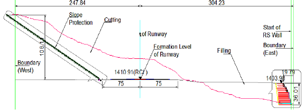
The runway strip is planned along N-S direction and the hill is having a natural slope from West (uphill cutting portion) to East (downhill filling portion) as shown in the typical cross section in Figure 3. Since a plane surface is required for the construction of the runway, cutting of uphill portion was done and the same material was filled at downhill portion to get the required level of runway. The constraint that material from cutting should be used in filling was mandatory. As such the entire project was designed in such a way that total volume of cutting shall be equal to total volume of filling. The terrain at site is mainly a mixture of soil and rocks. In upper strata, rock is fragmented and highly weathered. But with depth weathering decreases and soft to hard rock is encountered. Therefore, uphill portion is cut and used for the filling operation. This filling was retained by providing a suitable retaining structure high enough to support and stabilize the filling. Sikkim receives a very high annual rainfall; hence proper drainage system has to be provided along with the conveying structures of the existing creeks. This has been achieved by providing series of catchwater drains and stepped intercepting drains along with gabion cascades. Water from these cascades is finally conveyed outside the site boundary by RCC box culverts, which follows the natural course.
Hybrid MSE structures have been selected as the best possible solution as retaining walls in the filling side.
Design and Construction
The design of hybrid MSE structures has been carried out according to BS: 8006 code, for the static load case, while the seismic load case has been designed as per FHWA code. Load combinations for static load case and seismic load case (as per FHWA) have been adopted with the appropriate material and loading factors, according to BS 8006 and FHWA, and corresponding loads for various load combinations. External checks like sliding and bearing capacity were performed, and internal checks like reinforcement rupture and pullout; internal stability have been checked according to the “slices method for slip circle analysis” (as per section 7.4.4.3 of BS 8006). Sliding stability at steel mesh and geogrid interface and bulging check at nearly vertical gabion blocks have been calculated for all sections: 3 m length of secondary reinforcement have been considered and all the specified factor of safety requirements were achieved.
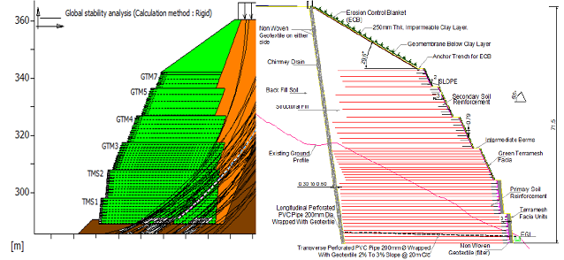
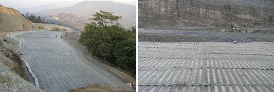
Design of primary reinforcement has been based on the properties of Maccaferri ParaLink geogrids, selected for the excellent creep characteristics and resistance to construction damages; geogrids with tensile strength from 200 kN/m to 800 kN/m have been designed, with vertical spacing up to 2.4 m. Totally 1.7 km length of hybrid MSE structures has been designed and built for supporting the airport runway. The most impressive structure is at Chainage 1640: the hybrid MSE structure consists of a 29 m high wall with gabion facing at bottom and a 51.35 m wrap-around slope above; an embankment of 6.61m height is present above the structure; thus the total height of the structure, including the embankment, is 86.96m. Design output and typical cross section for the highest hybrid MSE structure are shown in Figure 4. To Authors’ knowledge this is presently the highest reinforced soil structure in the world. Pictures of geogrids installation and of two finished hybrid MSE structures are shown in Figures 5 and 6.
SEISMIC DESIGN AND BEHAVIOR
Sikkim airport project lies in seismic zone IV, classified as severe seismic intensity zone according to Indian norm. For 70+m high structures located in seismic zone IV, the use of hybrid MSE structure was highly necessitated. Seismic design has been carried out as per pseudo static method described in FHWA manual. Reduction factors have been considered in calculating the long term design strength of primary geogrid reinforcement from its short term ultimate tensile strength. Seismic design has be carried out for considering load factors = 1.0 for all the loads. For seismic condition the target factor of safety for respective mode of failure is 75 % of static condition as per the guide lines of FHWA.
The structure was designed for horizontal seismic coefficient of 0.12.
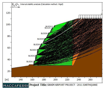
On 18 September 2011, an earthquake of magnitude 6.9 was felt across northeastern India (Sikkim), Nepal, Bhutan, Bangladesh and southern Tibet. The earthquake centered within the Kanchenjunga Conservation Area, near the border of Nepal and the Indian state of Sikkim. At least 111 people were killed in the earthquake and most of the deaths occurred in Sikkim. The peak ground acceleration for the earthquake of 6.9 on Richter scale would be 0.354 g. Horizontal seismic coefficient can be worked out as half of ground acceleration. Seismic analyses of full height structure with horizontal seismic coefficient of 0.175 shows that factor of safeties are just more than 1.0. Figure 7 presents the seismic analysis of typical cross section with horizontal seismic coefficient of 0.175, that is 45 % higher than the design seismic coefficient.

This means that hybrid MSE structures afford an inherent Factor of Safety which can be estimated to be approx. 50 % higher than the one resulting from design calculations with the present design Codes.
It is worth to note that the hybrid MSE structure have withstood an earthquake of 6.9 magnitude with no visible damage. This clearly demonstrates the resilience of hybrid MSE structure in seismic loading condition with higher vertical spacing of primary reinforcement.
Hence it is the authors’ opinion that the limit of 32 inches (800 mm) for the vertical spacing of reinforcement layers, reported in the present AASHTO regulations, should be relooked and the vertical spacing should be limited only by design optimization, at least for the hybrid reinforced soil structures described in this paper.
Pietro Rimoldi (pietro.rimoldi@gmail.com) is Geosynthetics International Specialist with Officine Maccaferri Spa, Zola Predosa, Italy. A. D. Gharpure (agharpure@maccaferri-india.com) is Director & COO of Maccaferri Environmental Solutions Pvt. Ltd., India. R. R. Mahajan (ratnwdc@maccaferri-india.com) is Div. Manager-Technical for Maccaferri Environmental Solutions Pvt. Ltd., India.


