
In this latest sharing of work from the GAP 2019 conference–Geosynthetica published GAP’s proceedings–Lyan Garcia and Jeb Tingle of the U.S. Army Engineer Research and Development Center (ERDC) share geocell research 40 years in the making. ERDC’s home in Vicksburg, Mississippi was also the site of the earliest geocell trials. Here, Garcia and Tingle report on new research motivated by the emergence of different geocell products/materials and geometries in the market. They evaluated different types of geocells in combination with good-quality and poor-quality fill materials with an eye on understanding how these combinations will perform in various airfield pavement repair applications. ABOUT OUR FEATURE PHOTO: A U.S. Air Force C-130J Super Hercules Aircraft from Dyess Air Force Base, Texas, takes off during Exercise Swift Response 16 at Hohenfels Training Area, Germany, June 17, 2016. (U.S. Air Force photo by Master Sgt. Joseph Swafford/Released). The airfield pavement repairs discussed herein, when combined with the recommended fiberglass foreign object damage (FOD) cover, are approved for C-130 operations on runways and taxiways.
AIRFIELD PAVEMENT REPAIRS & GEOCELLS
The concept of using sand-confinement systems, or geocells, as an expedient construction method for reinforcing pavement base courses above soft ground was first investigated by Webster and Alford (1978). The study focused on military truck traffic, and findings supported the use of geocells as a suitable construction technique where sand was readily available. The investigations were followed by Webster (1979,1980) to determine optimum geocell grid size (cell diameter and thickness/height), cell shape, geocell material, and minimum surfacing requirements for handling over-the-shore military 5-ton truck operations. A geocell with a height of 8 in. was recommended, although a geocell with a 6-in.-height was recommended if the sand had a good gradation. As cell area increased, the performance tended to decrease; the authors recommended cell areas of 36 to 44 square in. Among grid materials recommended for further evaluation were aluminum and plastic. Webster (1984, 1986) further refined the geocell technology into a high-density polyethylene (HDPE) grid that could be easily collapsed and then expanded on site to an area of approximately 8 ft. by 20 ft. of total panel size. HDPE strips were ultrasonically welded at intervals of 13 in. In a program sponsored by the Waterways Experiment Station in Vicksburg, Mississippi, geocells were demonstrated for military road construction and were ultimately proven as a practical solution for increasing the offload efficiency during over-the-shore operations. Webster (1986) published specifications for plastic grid sections as a result of these demonstrations, and the geocell concept was commercialized with the product called Geoweb®. At this point, however, geocells were still being evaluated for application to construction or repair of airfield pavements.
Read and Dukes (1988) investigated the use of geocells to reinforce the base course in bomb damage crater repairs to alleviate the requirement for high-quality, well-graded crushed stone. The repairs consisted of two layers of geocell-reinforced sand (16 in. total reinforced thickness) placed on a clay subgrade with a California bearing ratio (CBR) of 5. Each repair was surfaced with fiberglass matting and trafficked with a load cart simulating the F-15 aircraft (355 psi tire, 30,600-lb wheel load). Nearly all deformation occurred in the sand grid layers due to compression of the sand fill, local shear within the cells, and lateral spreading of the grids. The authors concluded that compaction was a major factor affecting performance and also recommended a coarser sand.
RELATED: Assessment of Historical Army Airfield Pavement Condition Data
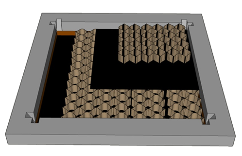
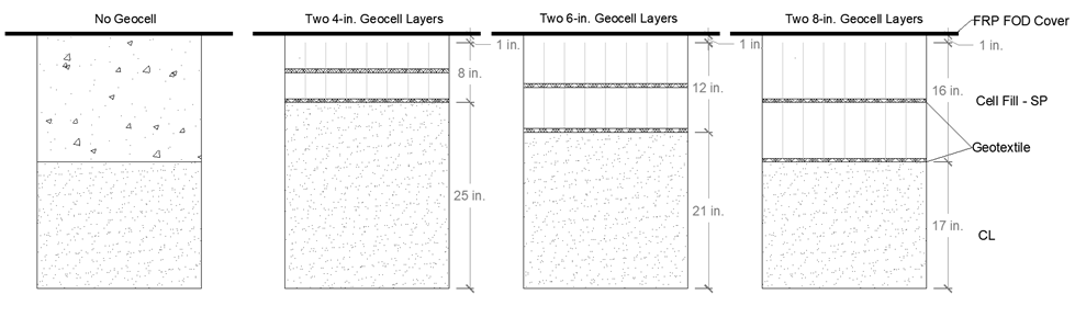
Since then, expedient airfield pavement repair with geocells has been established as a standard procedure with detailed methods included in the Unified Facilities Criteria (UFC): Airfield Damage Repair (UFC 3-270-07, 2002). When combined with the recommended fiberglass foreign object damage (FOD) cover, the repair method is approved for C-130 operations on runways and taxiways. Geocell reinforcement is a useful alternative to traditional backfill methods such as crushed stone or rapid setting flowable fill because lower quality backfill materials (i.e. indigenous materials) can be used to provide a temporary repair. The procedure requires two 8-in.-thick layers of geocell (Figure 1) filled with an indigenous material (ideally sand) placed perpendicular to each other over a minimum subgrade CBR of 4. Geocell material and geometry requirements align with the specifications of the geocell product.
New geometries and geocell materials have been introduced commercially for several years, but research that specifically addressed the use of new products for airfield pavement repair was limited. To address this capability gap, the U.S. Army Engineer Research and Development Center in Vicksburg, Mississippi initiated a research program that aimed at evaluating new geocell products/materials and geometries, and their combination with good-quality and poor-quality fill materials. Information from the program would help develop new product specifications and requirements for airfield pavement repair, and ideally validate other geometries and materials that are commercially available for this application. This paper summarizes the results of one of the objectives of the program, which focused on determining optimal geocell height(s) that could support modern heavy aircraft loads, such as the C-17 globemaster. Simulated repairs were built at the Waterways Experiment Station, trafficked with simulated aircraft loading, and deformation was monitored to measure the performance of the repairs.
MATERIALS
Sand & Clay
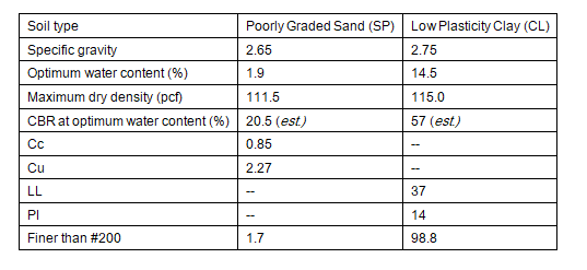
To evaluate the influence of geocells, the field experiments were carried out using a concrete sand as filling material. The material was classified as a poorly graded sand (SP) according to the Unified Soil Classification System (ASTM D2487). The geocell-reinforced SP was placed over a low plasticity clay (CL) subgrade to provide a uniform foundation throughout the tests. Specific gravity (ASTM D854) was determined for each soil, and modified proctor testing (ASTM D1557 – Method C) and laboratory California bearing ratio (CBR) testing (ASTM D1883) were performed on each soil. Physical properties of the soils are shown in Table 1.
Geocells & Geotextile
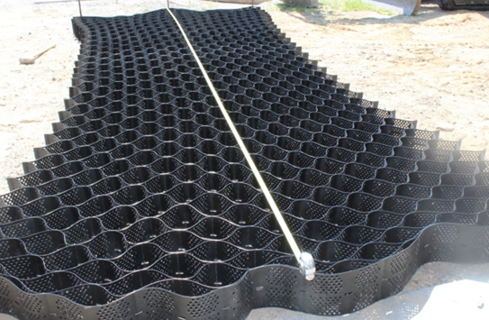
The geocells used in this study were made of high-density polyethylene (HDPE) strips that were textured, perforated, and ultrasonically-welded at intervals of 14 in. along their length. The system was expandable on-site to form a 3D grid structure. The individual cells were approximately 8.8 in. by 10.2 in. when the section was expanded. Three different geocell heights were evaluated: 4 in., 6 in. and 8 in. A photograph of a typical geocell section used in this study is shown in Figure 2.
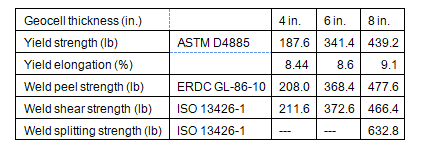
Measured mechanical properties for each geocell thickness, including the ultrasonic weld properties, are reported in Table 2. Peel, shear and splitting strength tests were conducted on the seams and failure occurred on the parent HDPE sheets at the perforations. A 6-oz, non-woven, needle punched, polypropylene geotextile fabric was used at the interface of geocell layers and at the surface of the CL subgrade layer.
Fiberglass-Reinforced Polymer (FRP) FOD cover
The Fiberglass-Reinforced Polymer (FRP) FOD cover panels are made of layers of glass fiber and aramid fabric impregnated with polyester resin (Rushing et al. 2016). A full-panel measured 18 ft. by 6.6 ft., and a half-panel measured 9.3 ft. by 6.6 ft. Each panel was connected using metal bushings and bolts. One repair required one full-panel and two half-panels. The leading and trailing edges of the repair were anchored to the pavement using a heavy-duty sleeve concrete expansion anchor.
EXPERIMENTAL PROGRAM
Experiment Layout
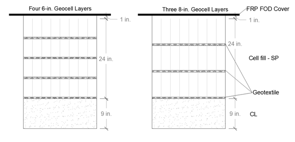
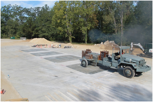
The field experiment was performed at the Outdoor Pavement Testing Facility, East Campus of the Waterways Experiment Station, Vicksburg, MS. Four (4) simulated craters were cut to 8.5 ft. square and excavated to a depth of 34 in. from concrete with a thickness of 15 in. A layer of CL was placed and compacted at the bottom of the repairs to provide a consistent subgrade throughout the tests. Two independent series of tests were conducted. Series 1 evaluated the 4-in., 6-in., and 8-in. geocell heights (i.e. different backfill reinforcement thicknesses), as shown in Figure 3. Series 2 aimed at validating the results of the first series of tests by reinforcing the same thickness of backfill (24 in.): 4 layers of the 6-in.-thick geocell and 3 layers of the 8-in.-thick geocell (Figure 4). The backfill in each series was SP. Each repair was surfaced with the FRP FOD cover. Simulated single-wheel C-17 aircraft traffic was applied to the finished repairs and deformation was monitored at different pass levels.
Construction
Each simulated crater was initially prepared by cutting the PCC surface with the 60-in. wheel saw attachment (SW60) on the compact track loader (CTL), which was representative of cutting around upheaval in a realistic scenario. Once the repair was cut to size, the PCC was broken into smaller pieces with the moil-tipped hammer attachment on the excavator. Large debris and material underneath the PCC surface were then removed with the bucket attachment on the excavator. Each crater was excavated to a minimum depth of 34 in. to ensure that a uniform natural foundation was reached. The CL layer was placed in approximately 3- to 4-in.-thick compacted lifts (5- to 6-in.-thick loose). Compaction of each lift was carried out by applying two coverages with a rammer. A coverage consisted of starting compaction in one corner of the repair and working towards the center of the repair in a circular motion, and then returning in a circular motion towards the corner where compaction began.
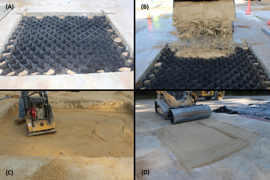
Once the surface of the CL layer was finished, the horizontal dimensions of the crater were measured so that the geocell sections and geotextile could be cut to size. Once geocell sections were cut, the installation of the geocell-reinforced SP for each repair was as follows (as recommended in UFC 3-270-07): (1) the surface of the CL layer was lined with the geotextile; (2) the first layer of geocells was expanded parallel to the centerline. Rebar was placed at all corners of the repair to hold the expanded geocell section in place, and SP was used to fill some of the geocell pockets along the edges to help hold the section in place (Figure 5a); (3) the geocell section was backfilled by dropping the SP vertically into the repair to avoid displacing the section (Figure 5b). The section was overfilled by approximately 2 in. and the SP was spread evenly; (4) the SP was compacted using a plate compactor (Figure 5c) until at least 2 coverages were completed. Any excess material was struck off level with the top of the geocells; (5) the surface of the first layer of geocells was lined with the geotextile; (6) the second layer of geocells was expanded perpendicular to the centerline and held in place, as described above; (7) the second layer of geocells was backfilled and compacted; (8) for Series 2 repairs, the next layer(s) were built using the same process. For Series 1 and 2 repairs, the top reinforced layer was compacted with the vibratory roller attachment on the CTL (Figure 5d). A 1- to 2-in. buffer of SP was placed above the top reinforced layer prior to installing the FRP FOD cover. The SP backfill in the control repair that did not have geocell reinforcement was built in 6-in.-thick lifts. Each repair was then surfaced with the FRP FOD cover.
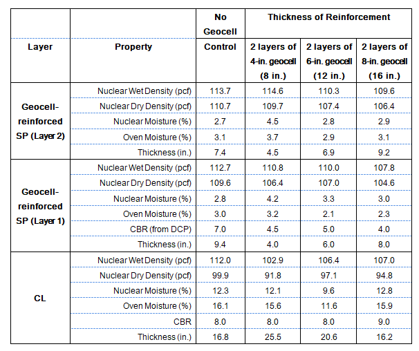
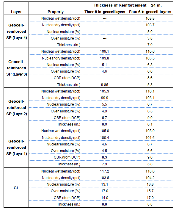
Data collection performed during construction included oven moisture (ASTM D2216), nuclear gage (ASTM D6938) and dynamic cone penetrometer (ASTM D6951) tests. Each lift was also surveyed to verify the thickness. The in-situ soil properties for both series’ of repairs prior to trafficking are reported in Table 3 and Table 4. Note that the CBR determined from the DCP at the top layer was not reported due to lack of confinement of the SP at the top 6 in. to 8 in.
Trafficking and Data Collection
Simulated traffic was applied to the repairs with a single-wheel C-17 load cart equipped with a 50-in. by 21-in., 30-ply tire inflated to 142 psi and loaded so that the test gear was supporting 38,500 lb (Figure 6). This weight represents the maximum load on one tire of a C-17 aircraft allowed in contingency operations. A normally distributed pattern of simulated traffic was applied in a 4.5‑ft.-wide traffic lane. Traffic was applied by driving the load cart forward and then backward in the same wheel path, then moving laterally approximately one tire width on each forward pass.
Data collection at each repair included rod and level measurements at the centerline and along two cross sections that were offset 3 ft. from the edges of the repair. Rod and level measurements along the cross section were taken on the loaded FRP FOD cover surface, where two (2) 2-kip blocks (much less weight than the load cart) were placed next the cross section. This was done in attempt to measure the deformation of the backfill throughout trafficking without having to disassemble the panels, since the FRP FOD cover tended to bridge over any deformation on the reinforced SP backfill underneath. All measurements were taken prior to starting trafficking, at different pass levels throughout trafficking, and after trafficking was completed. Measurements were also taken during construction and after trafficking was completed at each construction layer to measure the deformation at different depths. Failure of the repairs was defined as 3 in. of rutting on the FRP FOD cover surface.
AIRFIELD PAVEMENT RESULTS
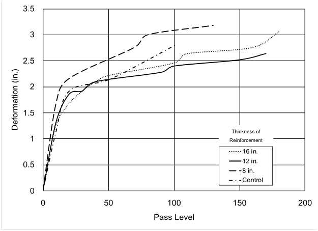
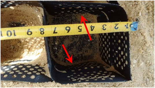
A summary of the deformation measured throughout trafficking of the Series 1 repairs is shown in Figure 7. Note that trafficking on all repairs had to be stopped after 3 in. of deformation were exceeded on the repairs with 8 in. and 16 in. of reinforcement. Instability of the load cart at these repairs made it difficult to access the other two repairs. However, sufficient data had been collected on all repairs for analysis. The rate of deformation at the repair with 8 in. of reinforcement was the highest, followed by the control (no geocell) repair. The repairs with 16 in. and 12 in. of reinforcement performed well and had similar rates of deformation. In general, 12 in. of reinforcement showed the best performance. Post traffic inspection of the repairs revealed cell wall buckling at the top and bottom layers of the 8-in.-thick geocells (Figure 8), where sand was displaced from adjacent cells and the wall bent. In all geocell-reinforced backfill repairs, cell penetration was observed, where the geocells pushed downward relative to the sand fill into the fabric membrane layer underneath; however, the geotextile did not tear as a result of this. Post-test deformation measurements at each layer showed that the deformation at the surface of the CL subgrade reduced as the thickness of reinforcement was increased, showing the effectiveness and impact of the geocell at distributing the applied load so as not to overstress the subgrade.
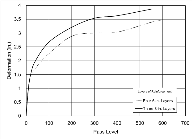
Since the 8-in.- and 6-in.-thick geocells both performed well and had similar rates of deformation, additional testing was performed to eliminate the variable of the thickness of reinforcement and the height of the CL layer relative to the surface of the repair (i.e. the effect of the subgrade on overall rutting performance). Series 2 aimed at specifically addressing the effect of geocell height on performance by making a relative comparison. The thickness of reinforcement was the same, but a different combination of layers was used (Figure 4). A summary of the deformation measured throughout trafficking of the Series 2 repairs is shown in Figure 9. The rate of deformation for the repair with three layers of 8-in. geocells was higher than that of the repair with four layers of 6-in. geocells, where the latter sustained nearly twice the number of passes before failure by deformation. Similar rates of deformation were noted when compared to the Series 1 repairs, which may be attributed to having moistures and densities closer to optimum in the Series 1 repairs. Cell penetration was observed at all of the layers, including the subgrade layer; however, the geotextile did not tear as a result of this. Post-test deformation measurements at each layer showed that the deformation at the surface of the subgrade was similar for both repairs and remained under 1 in.
Results from the Series 1 and Series 2 trafficking showed that an increase in the thickness of reinforcement provides increased protection to the subgrade, but there exists an optimum geocell thickness (6 in.) for protecting the subgrade. Better compaction can be achieved with thinner geocell layers, and the possibility of cell wall buckling is reduced with shorter geocell height. Based on these results, it appears that the 6-in. geocells are also applicable for airfield pavement repairs and can be used as an alternative to the traditional 8-in.-thick geocells used in this application.
SEE ALSO: Geosynthetics in Diverse Railroad Applications
RECOMMENDATIONS
This paper summarizes the results from full-scale testing of airfield pavement repairs using an SP backfill reinforced with varying thicknesses of geocells. The objective was to verify if a different geocell thickness could be used for this application instead of the 8-in.-thick geocells that are traditionally required for airfield pavement repairs. Geocell thicknesses of 4 in., 6 in. and 8 in. were evaluated in two series of full-scale tests.
With the exception of the repair with two layers of 4-in.-thick geocell (8 in. of reinforcement), the geocells improved the load-deformation behavior of the repair through lateral confinement of the SP. With an increase in the thickness of reinforcement, the geocell mattress was able to distribute the surface loading over a wider area to better protect the subgrade. However, surface deformation was higher for thicker layers of geocell. Compaction appeared to be a major factor in the performance of the geocells, where the 6-in.-thick geocells achieved better compaction. Although none of the reinforced SP layers reached 100% of the maximum dry density, Series 1 repairs with geocell heights of 6 in. and 8 in. had similar rates of deformation to Series 2 repairs, despite the fact that Series 2 repairs had 24 in. of reinforcement. Series 1 repairs reached at least 95% of the maximum dry density of the SP, while Series 2 repairs reached up to 93% (moisture contents were much higher than optimum). Based on the results of this testing program, a minimum of 12 in. of geocell reinforcement (two layers with 6 in. of reinforcement) is recommended for airfield pavement repairs. This is favorable for procurement because the 6-in.-thick geocells tend to be more readily available and are cheaper since they require less material. Note that the conclusions presented in this paper are based on the materials tested in this study under specific loading conditions.
Lyan Garcia and Jeb Tingle work with the U.S. Army Engineer Research and Development Center (ERDC). Learn more about ERDC’s engineering and research mission at https://www.erdc.usace.army.mil/.
REFERENCES
Rushing, T.M., Floyd, W. C., Garcia, L., and Mason, Q.S. 2016. Development of an Air-Droppable Airfield Damage Repair Kit. ERDC/GSL TR-16-25. U.S. Army Engineer Research and Development Center. Vicksburg, MS.
Webster, S. L. and Alford, S. J. (1978). Investigation of Construction Concepts for Pavements Across Soft Ground (No. WES-TR-S-78-6). U.S. Army Engineer Waterways Experiment Station, Vicksburg, MS
Webster, S. L. (1981). Investigation of Beach Sand Trafficability Enhancement Using Sand-Grid Confinement and Membrane Reinforcement Concepts. Report 2. Sand Test Sections 3 and 4 (No. WES/TR/GL-79-20). U.S. Army Engineer Waterways Experiment Station, Vicksburg, MS.
Webster, S. L. (1979). Investigation of Beach Sand Trafficability Enhancement Using Sand-grid Confinement and Membrane Reinforcement Concepts: Sand test sections 1 and 2. Report 1 (Vol. 79, No. 20). U.S. Army Engineer Waterways Experiment Station Vicksburg, MS.
Webster, S. L. (1986). Sand-grid Demonstration Roads Constructed for JLOTS II Tests at Fort Story, Virginia (No. GL-86-19). Waterways Experiment Station, Vicksburg, MS.
Read, D. L. and Dukes, P. E. (1988). Sand Grid Base Course Phase I, for Fiberglass Ma Crater Repair. RRR-TR-88-01. Air Force Engineering and Services Center, Tyndall AFB, FL.
UFC 3-270-07. 2002. United Facilities Criteria: Airfield Damage Repair.


