
In the latest addition to our GeoAmericas series of stories, we look back at the GeoAmericas 2016 project story of how Groupe Alphard utilized electrical leak location (ELL) surveys and a customized quality control (QC) program to improve a gold mine closure project near the Arctic Circle in the Northwest Territory of Canada. The QC approach and leak location technology, described here by Carl Charpentier, and TJacquelin is notable for the harsh environment in which it was conducted, the work with a bituminous geomembrane system, and the execution of the work in an environmentally sensitive location. Geosynthetica published the GeoAmericas 2016 proceedings. International Geosynthetics Society members can download the full proceedings volumes for free after logging into the IGS website and visiting the proceedings resources section.
1. WORKING NEAR THE ARCTIC CIRCLE
Tundra Mine, located approximately 250 km northeast of Yellowknife, is a former underground gold mine that was operational in the 1960s, with the mill put into operation again in the 1980s to process ore from Salmita Mine. The Government of Canada was charged with awarding the contract for the remediation work of the site.
The site has three main areas: the mill site, off-site areas, and the tailings containment area (TCA), which consists of the Lower Pond, the Upper Pond, and the related dams. The tailings from the mill were deposited directly into Russell Lake. In the 1980s, containment dams were constructed around the tailings pond, with another dam constructed later which divided the pond into the Upper and Lower ponds, in order to allow for water cover over the south portion of the TCA. To bring these three areas to near pre-mine conditions, the site remediation was divided in two phases. Phase I mainly consisted of dealing with the structures and equipment, waste material, dumps and debris, and mine openings. Phase II incorporated the environmental aspects: the decontamination of the water in the two ponds (which began in 2009), and the consolidation of the dried tailings and waste rock into the Lower Pond. The water from the ponds contained arsenic that had to be treated prior to release, and the waste rock is potentially acid generating (PAG) and some has hydrocarbon contamination (URS 2005).
To ensure that the tailings and waste rock would not contaminate the surrounding environment, it was planned that they would be landscaped in the Lower Pond into a relatively flat surface with a small slope for water runoff. The area would then be capped with geosynthetics (230,636 m2), thereby separating them from any rainfall or surface water (AECOM, 2012). According to the initial design, ES2 Bituminous Geomembrane (BGM) was to be the sole geosynthetic material used, however, later changes to the design also incorporated LP 16 Geotextile for added security and protection.
RELATED: Cold Weather Watch: Rapid Crack Propagation in Geomembranes
This paper will focus solely on the quality aspects of the capping of the mining wastes, specifically Groupe Alphard’s evolving role in terms of providing quality control (QC) and electrical leak location (ELL) in the 2012-2014 seasons, and improvements that were brought to the design and work methods as a results of Groupe Alphard’s presence onsite and the testing they performed. The work had to evolve based on the unique site conditions found at Tundra Mine (short summers, northern climate and geography, remote site with a large area of mining wastes to be covered with BGM) and the lessons learned from one season to the next. By adapting the design and work methods based on concrete visual and testing evidence from the QC supervision and ELL surveys, a higher quality system was constructed.
2. DESCRIPTION OF THE SITE
A remote site, located in the tundra, the land around the site is generally flat, with rocky outcroppings and numerous water bodies. This near Arctic site is located in an area with permafrost. In certain areas in the Lower Pond, water was present just below the surface to be covered, and the mining wastes could be subject to frost heave. In the summer, the site is accessible via charter flight once a week from Yellowknife. Personnel and supplies are brought to a small landing area near the site, which connects to the site via an access road. Larger supplies and equipment can only be brought to site in the winter by ice roads.
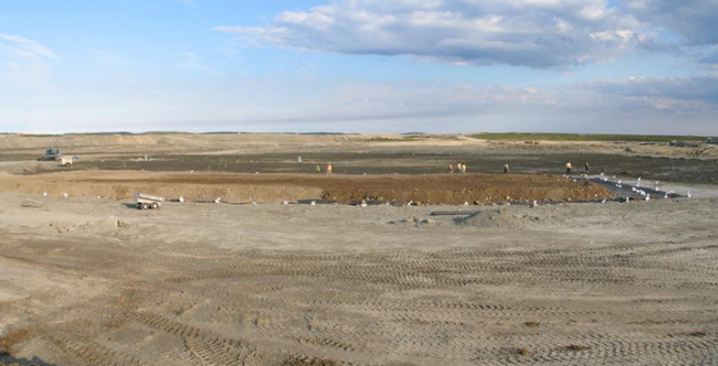
The summer season is short (June – September). The weather can be unpredictable and change rapidly with the sudden onset of winter conditions. The construction season is therefore highly dependent on the weather, which must be considered at all times nearing the end of the season. However, the summer does provide generally 24 hours of daylight, and certain work can continue into the night.
Another consideration onsite, which is not normally an issue for containment works in urban areas, is wildlife. Migratory animals and bears do pass near the area. Although this does elicit the obvious considerations of risk to human life, animals can also damage the work, or delay schedule until they have cleared the area.
3. INITIAL MANDATE
With the installation of the BGM scheduled for the summer of 2012, the materials and equipment had to be brought onsite via the winter roads. They were therefore handled and stockpiled prior to Alphard’s arrival. Supervision of these activities is generally a part of a comprehensive QC program, to ensure that there is no damage to the geosynthetics, and that the storage methods will not harm the integrity of the material.
Electrical leak location was not mandatory at the Tundra Mine remediation site, however after being awarded the QC mandate, Groupe Alphard recommended adding electrical leak location using the dipole method. Performing the dipole survey would help to validate the work methods and the materials for both the installation of the geomembrane and the cover material overtop.
In 2011, it was decided between the contractor and the federal government that the dipole survey would be performed on a test pad area (the corner of the capping) once the BGM installation had begun, to validate the quality of the work and to prove the pertinence of performing the leak location survey over the entire capping.
From bottom to top, the design of the leakproof system consisted of:
- Mining wastes (tailings and waste rock)
- Bituminous geomembrane
- 1,200 mm to 1,700 mm thick covering made of a mix of sand and rocks not to exceed 150 mm diameter (Type A)
The contractor was responsible for executing the above works, including the earthworks (ensuring a firm, to grade, subbase with no large or sharp rocks, and placing the cover material) along with the installation of the BGM, despite not being a dedicated geomembrane installer.
Based on the leak location company’s experience with field tests and numerical modelling, it was recommended that the cover material be installed in two steps; the dipole test would be conducted on the first 750 mm of the cover material, with the balance of the material installed after the survey. Generally, most damage to the geosynthetics would have occurred after the installation of the first lift, and there is less potential for damage during the placement of the remaining layer. This method was accepted for the test pad and leak location demonstration. Additionally, other requirements were expressed to enhance the dipole sensitivity, such as electrical isolation of the cover material along the periphery of the area to be tested, access to a water truck to moisten the top of the cover material (if necessary), and a power generator for the dipole power source.
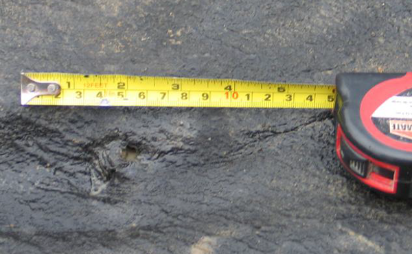
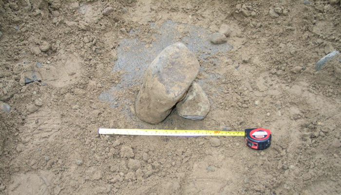
Finally, three test pads were constructed with different configurations. On the first test pad, measuring approximately 1,800 m², a total of 7 leaks were found, with a cover material thickness between 700 mm and 1,020 mm. All leaks were punctured through and ranged in size from 5 mm to 150 mm (see Figures 2 and 3). Upon further inspection it was noted that the subgrade surface on which the BGM was placed was not suitable, and that the cover material was not properly screened (rocks too large and too sharp, as shown in Figure 4). Boulders were found in the subgrade and cover material ranging up to 800 mm.
On the other two test pads (1,400 m2 and 600 m2 respectively), different systems were built with geotextiles for added protection. Although no holes were found in these two tests pads, and the geotextile certainly did help, more care was also given to the screening of the materials. For the 2012 season, including the three test pads, the average hole frequency was 18.42 leaks per hectare.
As no leak location survey was performed on the material prior to it being covered, it is cannot be said if any of those leaks were present prior to the installation of the cover material (even without it being subject to loading). The outcome was that both the subgrade and the cover material needed to be better screened, and some additional protection was needed for the bituminous geomembrane. Protective geotextile was added to the design: one below the BGM to protect it from the subgrade and one above to protect it from the cover material.
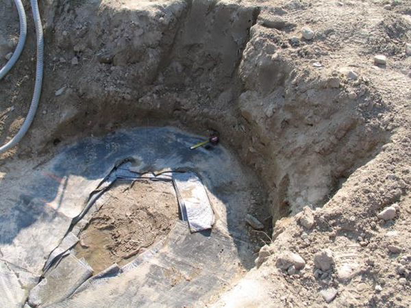
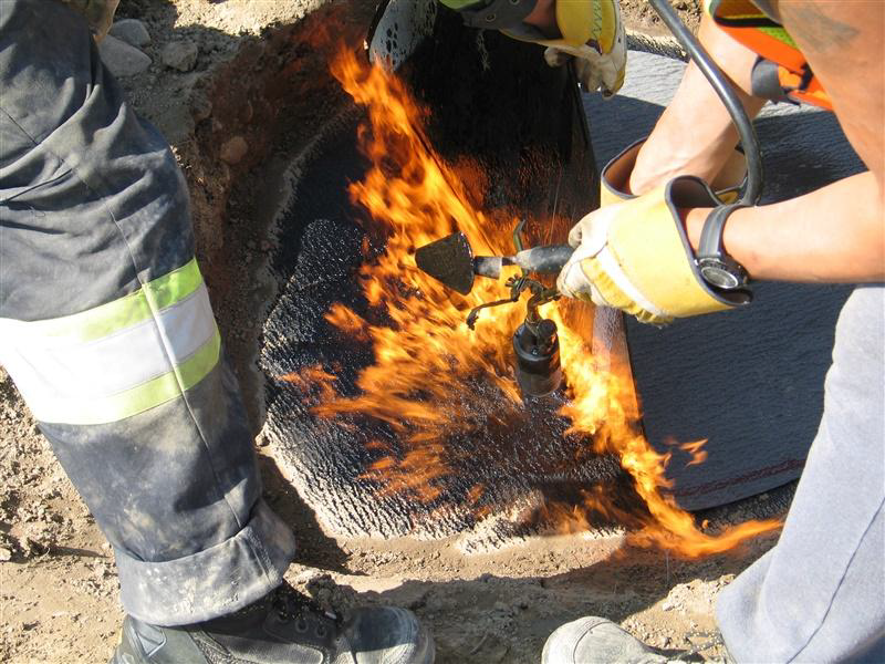
The site parameters and the type of material used had an interesting effect when performing the repairs. Firstly, when a leak was detected using the dipole method, the cover material had to be excavated to find the extent of the defect. With other types of geosynthetics, only a small work area needs to be cleared around the defect to perform the repair, therefore a similar sized area was excavated for the BGM repairs. With BGM however, repairs are performed by heating and melting the bottom of the patch with a torch onto the area needing to be repaired and then ensuring that the entire periphery is well sealed. Given the small work area cleared, as well as the “tunnel” from being surrounded by 700 mm to 1,020 mm of cover material, the flames from the torch enveloped the small work area (see Figure 5). A larger area was therefore necessary for repairing the BGM defects.
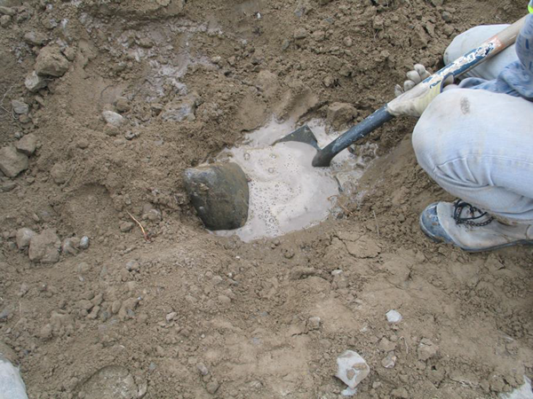
The other interesting effect, which was caused by the arctic location of the site, was the permafrost impact on the geosynthetic work. Since the BGM was black, it was heating up under the sun, and melting the permafrost in the ground. With the cover layer installed, a pressure was applied on the water trapped under the BGM. The impact was seen when the cover material was removed to unearth a hole and all of the pressure was applied to the area excavated; the BGM mounded with the water underneath, and when opened, a fountain effect was created through the leak. It was a challenge to repair those defects considering the amount of water compressed under the membrane that was constantly flowing through said repairs (see Figure 6).
As it was already late in the season, and no new material (geotextile) could be brought onsite, the construction work was put on hold for the 2012 season, with plans to implement changes to the design and installation methods in 2013 based on the findings of the leak location survey. These test pads helped determine the best method for installation.
4. MODIFIED CONSTRUCTION WORK AND MANDATE
In 2013, Groupe Alphard returned to perform ELL and QC, with the modified QC program. As the geotextile was added to the design and the materials were to be better screened, the dipole survey was not to be performed, only the water puddle survey. The water puddle survey is performed on the exposed geomembrane in order to find any holes that are present during the installation of the membrane itself. Another ramification of adding the geotextiles was that the depth of the cover material was decreased to 600 mm.
The installation period in 2013 was slow to start. The subgrade needed a lot of work, as there were still many rocks, and the new QC program took some time to implement. A new team dedicated to geomembrane installation was hired to perform the work.
The more stringent QC parameters were instated and enforced, in order to help to decrease the defects. A greater effort was put into preparing the subgrade to ensure that the BGM would not be damaged once placed.
In the end, only 6,300 m2 of BGM was installed, on which 3 pinhole leaks were found with the water puddle method, giving a hole frequency of 4.76 leaks per hectare. In general, compared to 2012, the holes were smaller and the average hole frequency was decreased. The leaks were not due to the subgrade or the cover material, but rather resulted from the installation itself. In the end, the area was not covered and no dipole survey was conducted, however, given the extra care that was put into the subgrade preparation, it is obvious that had the dipole survey been conducted, the hole frequency would have been much lower than in 2012.
5. CONSTRUCTION WORK
In 2014, the quality control and water puddle survey mandates were once again performed, given the favorable quality improvements from the previous year. However, as an added quality measure, the dipole survey was to be performed to ensure that the natural materials and/or the work methods did not negatively impact the geosynthetics. The survey was performed on the full depth of the cover material (600 mm). The same stringent requirements were upheld in 2014 in terms of installation of the materials and the quality of the subgrade and cover materials. Another change from the previous years was that a new geosynthetics installer was mandated to perform the installation.
For the water puddle survey, a total of 32 leaks were found in the areas installed during the 2013 and 2014 seasons. The area installed in 2013 was re-tested to ensure that no damage occurred to the geomembrane over the winter due animals, human traffic, or winter conditions. No leaks were found in this area. The geomembrane did not appear to have been under undue stress from frost heave or rocks in the subgrade, which may be attributed to the extra care given to the subgrade in 2013. In total, 132,477 m2 was surveyed using the water puddle method, giving a hole frequency of 2.42 leaks per hectare, a significantly lower rate than in the previous years.
Tears and punctures accounted for a large portion of the defects, as did some seaming errors. What is interesting is that faults in the material itself also accounted for some of the defects. This may be attributed to improper handling or poor storage over 3 years—longer than material is generally stored onsite for and in harsher conditions. The size of the leaks ranged from not visible to the naked eye to 6-7 cm.
RELATED: Reducing Well Pad Construction and Maintenance Costs
The again lower hole frequencies, as well as the types and size of the defects, show the evolution of the site and people’s understanding of the important factors onsite. Initially the holes were primarily due to poor cover material and installation methods. In 2014, the leaks were smaller, and caused by a greater variety factors, indicating the leaks could not be attributed to one source – in general, neither the materials nor the methods were faulty.
For the dipole survey, only a portion of the installed area was surveyed. In order to expedite the survey, and reduce costs, it was decided that 100% of the first 10,000 m2 of cover material would be tested using the dipole method. If no leaks were found, then in the following 10,000 m2 only 50% would be surveyed. If again no leaks were found, then the remainder of the site would only have 25% of its area surveyed (unless a leak was found). In the areas where less than 100% was surveyed, the technician surveyed by increasing the size of the grid. Although not 100% of the surface was surveyed, under good conditions (proper isolation and good electrical conductivity) a leak can still be detectable.
Additional measures were also taken to prove the efficacy of the dipole survey, and that the installation methods did not hinder the quality of the geomembrane. Prior to commencing any dipole survey, a “leak simulation” is placed just on top of the geomembrane, with the cover material re-installed, in order to determine if the equipment can detect the “artificial leak” given the site parameters. In addition to this, and specific to this site, a real hole from a stake being driven into the BGM was tested. The leak was detected by the dipole technician, thereby validating the method under “real-life” conditions, and showing that the geotextile did not inhibit the method.
Another way in which the work methods and materials were validated was by digging 13 randomly selected tests pits that were 3 m by 3 m in size. No damage was apparent to the membrane, including leaks or large wrinkles. This can be attributed not only to the changed materials and methods, as previously stated, but also due to visual inspections during the installation of the cover material, to ensure that the material was not stressed, a key, often overlooked, component of QC activities.
These two tests helped to validate not only the installation of the materials and the materials themselves, but also supervision of the installation of the membrane (QC) and the testing methods (ELL). Additionally, it helped to highlight quite dramatically the differences in the results from the 2012 season: 18.42 leaks per hectare found with the dipole survey in 2012 (all related to the quality of the natural materials), versus no leaks found with the dipole survey in 2014 (all of the leaks were present during the installation of the BGM, not due to the natural materials). The changes, despite being slow to adapt to, in the end allowed for proper material and methods to be used, and therefore quality containment works. The testing and test pits helped to give assurance that there were no buried faults that would become apparent in a few years after the site had been subject to winter conditions.
6. CHALLENGES AND UNIQUE CIRCUMSTANCES ENCOUNTERED DUE TO SITE CONDITIONS
Certain specific circumstances were encountered on this site due to its remote northern location, the size of the area to be covered, and the type of geosynthetics used.
6.1 Winter
The fact that the installation work, and related QC and ELL activities, proceeded well into the winter season in the tundra produced its own set of challenges. A weather scare at the beginning of September 2014 helped bring to mind that snow, and the winter freeze, could hit at any time when working this close to the Arctic Circle. Although BGM installation can be performed under a wider range of climactic conditions than HDPE geomembrane, colder conditions and snowfall can reduce installation speeds or can prevent installation altogether. Cunning et al. estimated BGM installation rates were 33% slower in the winter than in the summer at the Diavik site (2008). Additionally, neither of the ELL methods used onsite can be performed when the subgrade (and/or cover material) are frozen. ELL is based on the electrical conductivity of soil, which decreases significantly when the medium is frozen.
The water puddle survey had to follow the BGM installation as closely as possible—without interfering in the installation process—as all of the subsequent steps relied upon it. Although BGM installation is dependent on weather conditions, geotextile installation can be performed under non-ideal conditions (modifications to the installation methods were made to accommodate wet geotextile that could not be heat tacked), as can cover material placement. Therefore, to not cause undue delays, all BGM installed had to be validated as quickly as possible, in case of poor weather days, so that some work could continue even if leak location and BGM installation could not. This became much tougher to manage once temperatures started dropping below zero at night and into the morning. Either the water in the hoses became frozen overnight or all of the equipment had to be stored indoor – both of which cut into survey time.
For the dipole survey, although other steps were not dependent on it being completed prior to them commencing, it regardless needed to be completed before the soil became frozen. Otherwise any areas not surveyed would have to be very clearly demarked and surveyed the following year. This is not always reliable, as any physical markers can become damaged, or information can be lost or miscommunicated over multiple months and change of personnel.
6.2 Large Scale
Another interesting aspect of this site is the sheer size of the area to be covered. Whenever a substantial area was installed, it quickly had to be validated and “closed off” to ensure that nothing was forgotten (repairs, rocks pushing through the BGM which were only evident after the fact).
It was not always obvious to find a repair from a few days previous when the site is proceeding at a fast pace; there are personnel switch-outs (where information is not always transferred accurately), and miscommunications (markers are mistakenly misplaced). Also, as the night shift would install the cover material, clear instructions had to be given if there were repairs to be made, so that they would not be covered.
As the site was large, work did need to continue into the night to obtain the level of production necessary. This had two effects: firstly, it was necessary to ensure that the earthworks team had sufficient completed area on which to install cover material, otherwise there would be a loss of productivity. This entailed leaving expanses of geotextile uncovered into the night. This had the negative effect that if there were high winds, any installed geotextile that was not sufficiently ballasted would come apart and be displaced. Under ideal weather conditions, this would entail a few hours of delay (for both the earthworks, who could not install any further, as well as the geotextile installers), however, if the geotextile was wet and temperatures below freezing, then work could not progress until the geotextile became unfrozen. Another effect was that there was no QC oversight at night to ensure that the installation of the soil was done in such as a way as to not damage the liner. Again clear instructions had to be given, however there was no way to verify the next day if it was done properly, as any large wrinkles or tears might have been covered. Despite being in an area with 24 hours of daylight and spotlights, the site was not as well lit at night as during the day, and mistakes can be overlooked. In this way, the dipole and the test pits helped to give some assurance and peace of mind in that respect.
6.3 Remote Location and Equipment
BGM has a rough texture that caused the leak location equipment (wires, hoses) to become frayed and worn. When the wires became frayed, it caused false signals to be produced. The equipment therefore had to be continuously maintained. More materials or replacement equipment could only be brought in once personnel switch-outs occurred, which was sometimes greater than a two-week period. The cold weather and long working days similarly had a negative effect on the equipment, such as the pumps, and spare parts had to be found from the equipment onsite.
7. LESSONS LEARNED AND CONCLUSION
The decision to modify the design and the methods of work from 2012 to 2014 had a great, positive impact on the quality of work, as evidenced by the low hole frequency in 2014 and the visual inspections of the test pits. In 2014, the only defects detected were those from installation or the material itself (not uncommon for installation – as no installation has zero defects). The adaptability and evolution based on lessons learned from one season to the next allowed for a positive quality improvement (18.42 leaks per hectare in 2012 versus 0 leaks found in 2014 using the dipole method). But, going forward, what should be done to prevent these delays, and still maintain the quality of work required?
Winter hits early in Tundra Mine. By early September the first snowfall had already arrived, and although the snow was quick to melt, it was a warning that extra precautions would be needed. With such a short installation season, no delays could be afforded, and each phase of the work had to follow the other closely.
In order to have quality work from start to finish, you must plan for quality work from start to finish. Having quality work in one step of the project is meaningless unless you have quality work throughout all stages of the project. This is especially true for work in remote locations where any change in methods or materials, or even contractors and personnel, will have a huge impact on schedule (dependent on ice roads, and under tight time constraints due to short construction season and harsh winter conditions). Having the right equipment and proper materials (whether it be heavy equipment, or small replacement parts) to perform the job is essential for any project, but for remote sites there must be options for operating under non-ideal conditions, especially if backup equipment or materials are not available that week, month, or even year.
It is important to point out that even if electrical leak location was not planned onsite at early design, it was still the only way to measure the performance of the mining cap project. It is clear that had the leak location not been performed, and the work methods continued, then the final product would not have given the technical performance necessary. If the presence of rocks was able to cause issues before even being subject to frost heave, and improper techniques and materials were used even with two levels of oversight (immediate QC supervision and post-validation with ELL), then the issues would have been greater later on. The BGM would have been subject to even greater load (not all of the cover soil had been placed and in the winter it would be under the weight of snow and ice), as well as frost heave from below. As the location is remote, unlike in an urban area, any problems would not be noticed immediately, if at all. The only way to ensure that the surrounding areas would not be contaminated, from improper installation or materials, was by performing electrical leak location.
This case study demonstrates that a standard quality control program for the installation of bituminous geomembrane is not always adapted to uncommon environment and harsh conditions such as those encountered on remote, near Arctic northern locations. Applying a customized QC program adjusted to site conditions and paired with appropriate ELL survey has shown a significant improvement of the quality of the installed BGM. This approach has certainly brought the installation closer to the global performance anticipated for the mine closure.
Carl Charpentier, and TJacquelin are with Groupe Alphard, Montreal, Canada.
REFERENCES
AECOM. (2012). Tundra Mine Phase II Remediation Tailings Containment Area (TCA) Cover Design Report. Prepared for Public Works and Government Services Canada. August 3, 2015.
Cunning, J., Isidoro, A, Eldridge, T, Reinson, J., (2008), Dam Construction at Diavik Using Bituminous Geomembrane Liners, GeoEdmonton’08, GeoEdmonton’08 Organizing Committee, Edmonton, Canada, 933-939.
URS Canada Inc. (URS). (2005). Phase I Remedial Action Plan, Tundra Mine, NWT. Prepared for Public Works and Government Services Canada. August 3, 2015.


