 When GeoAfrica 2013 convenes in Accra, Ghana 18-20 November 2013, Prof. Malek Bouazza (Monash University) will deliver one of the keynote addresses on a subject dear to Ghana’s continuing development: mining. Prof. Bouazza will focus on the many ways geosynthetics have, can and should be utilized in mining. Here, we publish a summary of “Geosynthetics in Mining Applications: What have we learned?” from the keynote paper authored by Prof. Bouazza, Will Gates (SmecTech, Monash University) and John Scheirs (ExcelPlas). The full paper and presentation will be available at GeoAfrica 2013. Here in Part 1, the use of geosynthetics in containment is touched upon. In Part 2, the focus is on reinforcement. – Chris Kelsey, Editor, Geosynthetica
**
The use of geosynthetics in various mining operations is increasing rapidly. While they have not been accepted as readily as in the civil engineering industry, growth in the mining industry is occurring as operators begin to understand the advantages associated with the use of these materials. The extreme ranges in leachate properties generated from the various ore extraction processes, the harsh environment to which geosynthetic materials are exposed and the extremely large normal loads they are subjected to, are extremely challenging.
GEOMEMBRANES: HEAP LEACH PADS & CONTAINMENT FACILITIES
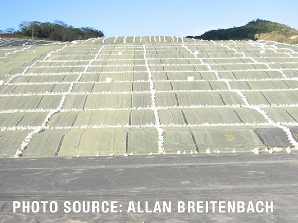
Geomembranes are designed as relatively impermeable liners and have been extensively used, over the past two decades, in barrier systems for waste containment facilities for a large spectrum of waste including mining waste. They have become critical components in mining facilities where their containment performance has been proven. These include base liners for heap leaching pads, liners to concrete basins and tank liners, solar (or evaporation) ponds for salt recovery, temporary exposed liners or “raincoats” for tropical sites, interlift liners in heap leach pads, liners for mitigation of acid mine drainage (AMD) from tailings or waste rock dumps and for tailings and process residues impoundments.
Smith (2008) indicated that there is a strong correlation between metal production and geomembrane demand and that both are interrelated and driven by similar economic factors. Furthermore, he stressed the fact that this relationship is expected to continue and to be amplified with increasing use of heap leaching and diversified applications such as tailings and acid mine drainage control.
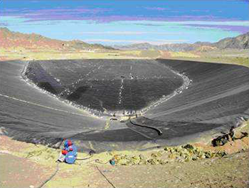
Heap leach pads are generally constructed utilizing as much as possible the natural topography of the site in a variety of climates ranging from arctic (temperatures as low as -30oC), tropical wet (rainfall exceeding in some cases 2.5 m/y) to dry Saharan climates (temperatures as high as +50oC) and at altitudes above 4000 m (High Andes of South America). The pad area is cut and filled as required, and trimmed to achieve a desired slope of 0.5 to 1%. HDPE or LLDPE are normally used for the base of the pad with the liner being between 1-1.5 mm thick over the pad and between 2-3 mm thick in the sumps and drains. Directly over the liner are installed (generally HDPE) drainage pipes, which are covered by a layer of about 60 cm granular protective soil layer to protect the geomembrane liner-pipe system during ore stacking. Contrary to the practice in the landfill industry, geotextile protection layers are seldom used in heap leach pads.
The geomembrane lining material is used to retain chemical solution used to dissolve minerals from ore, and to allow the leachate to be collected and refined. Heap leaching presents a combination of extreme base pressures and high moisture/acidity conditions on the geomembrane not present in any other containment application. These extreme conditions push the envelope of known geomembrane performance often beyond the recommended general design limits, and include ≥ 100 m high heaps, equipment loading of up to 53 tonnes per wheel, coarse rock overliner, concentrated acid or alkaline exposure, hydraulic heads of up to 60 m, liquefaction potential and harsh arid climates with daily temperature extremes (Thiel and Smith, 2004). The combined action of aggressive solutions and temperatures reaching up to 60oC to 70oC on an exposed geomembrane surface can seriously soften most liner materials. Furthermore the dumping of ore on the liner necessitates a strong and flexible geomembrane that is resistant to abrasions and punctures. Finally the steep, angular design of the collecting ponds requires a strong, durable product. For lined mining facilities subjected to moderate to high loads (greater than 300 kPa), geomembrane materials such as HDPE, LLDPE, and (to a lesser extent) PVC are used, mainly because of industry experience with these materials and documented performance from constructed mine facilities. However, geomembrane-lined heap leach facilities are being designed with ore heights approaching 240 m, resulting in normal stresses in excess of 4 MPa (Lupo 2010) presenting, in this respect, new challenges to the geosynthetics industry.
Mining is the backbone of many economies around the world, including developed countries such as Australia. In many developing countries it provides more than 50% of the export earnings, for example in Papua New Guinea it represents 66% of the earnings (Fourie et al. 2010) compared to 42% in Australia (MCA, 2009). Therefore, it is not surprising that the mining industry is often found to be the single largest producer of solid waste around the world, sometimes orders of magnitude higher that other forms of solid waste (e.g. municipal solid waste). If one considers that in order to recover a gram or two of gold, one tonne of mineral bearing rock must be crushed and processed, and at least another tonne of waste rock is produced, an idea can be gained of the enormity of the waste management problem faced by the mining industry.
In Australia, the annual total production of mining waste for 2012 was about 6.5 billion tonnes making the scale of landfills pale into insignificance at just hundreds of millions of tonnes (Mudd, 2013). Blight (2010) reported that the South African gold mining industry produced 740 000 tonnes of gold tailings in the decade from 1997 to 2006. Prior to 2000 the total tailings discharged from mills in China were about 5026 million tonnes. After 2000, the annual tailings discharged reached nearly 600 million tonnes (Shen et al., 2011).
A considerable proportion of the mining industry has shifted to large scale open cut mining techniques which invariably require the removal of significant quantities of waste rocks. This is also coupled with a general trend of declining ore grades meaning that higher quantities of ore need to be processed to produce a given unit metal or mineral (Mudd, 2009). Fourie et al. (2010) indicated that when one considers the enormous volumes of mining waste produced annually, and the potential environmental risks associated with storage of these wastes, it is striking to note that the vast majority of geosynthetics usage in the industry is not related to this application. It is related to production activities (e.g. heap leach pads, etc.). Christie and Smith (2013) indicated that essentially 100% of leach pads are lined with at least one geomembrane and the average leach pad now exceeds 1M m2 in lined area. They also indicated that in the copper industry, less than 1% of the area of tailings facilities are lined with geomembranes. For gold the number was larger and increasing, but remained well under 50%.This is not entirely surprising, because companies are in the business of mining to make a profit and anything that improves productivity is likely to be embraced wholeheartedly. Environmental protection on the other hand, is simply a cost and generates no income stream.
Mining waste comes in two primary forms: waste rock and tailings. In any mining operation, in order to access the valuable, mineral bearing rock, it is first necessary to strip or excavate non-mineral bearing rock. This rock, which has been fragmented during drilling, blasting and excavating process, is dumped in dedicated storage areas, known as waste rock dumps. Tailings on the other hand are the by-product of the crushing, milling and chemical extraction process used to recover the valuable mineral being mined. Tailings are generally sand sized or finer, and are managed by pumping at low solids contents and deposited into purpose-built impoundments, known as Tailings Storage Facilities (TSFs). The storage of these very large volumes of waste rock and tailings results in storage facilities that cover very large areas of land. Some of the oil sands TSFs exceed 100 hectares, and areas exceeding 120 hectares are not uncommon in base metal, gold and platinum mining operations (Fourie et al., 2010). Solid tailings are in most cases mixed with water and pumped to the tailings storage facility (TSF), sometimes over large distances (in excess of 5km). Upon deposition, large volumes of water separate out from the solid material, and this water must be stored and managed in such a way that it poses no risk to the environment. Unlike landfills where the leachate head on the underlining system is restricted, usually to around 0.3m, the hydraulic head acting on a TSF liner system can be several meters. TSFs are increasingly lined to minimise the possible contaminants migration. Dillon et al. (2004) provide an insight on the largest fully lined (geomembrane + geosynthetic clay liner) tailings storage facility in Europe located in Ireland. Lupo (2009) indicated that several TSFs have been lined in USA. Fourie et al. (2010) indicated that bauxite residue disposal sites, where the very high pH and salt load of the leachate, often coupled with the proximity to residential areas, has resulted in mining companies such as Alcoa World Alumina and BHP-Billiton voluntarily implementing the installation of lining systems.
GCL INTERACTION WITH MINING WASTES
The scarcity of suitable and economical clayey soil resources for traditional liners (i.e compacted clay liners) throughout mining localities has resulted in recent increased interest in alternative hydraulic barrier materials, such as geosynthetic clay liners (GCLs). Just as for other liner systems, the application of GCLs in a mining environment (ex., uranium mill facility liners, brine evaporation ponds, waste rock dumps, etc.), generally pushes their performance beyond recommended limits typical for other environmental and engineering applications (Gates et al., 2009, Bouazza and Gates, 2013).
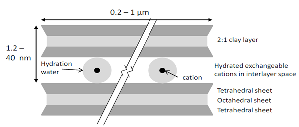
for Na+-montmorillonite are a measure of one dimensional clay swelling. The interlayer distance (and
volume) increases with uptake, or decreases with release, of water by the interlayer cations and the
crystallite surfaces (from Bouazza and Gates, 2013)
Our understanding of the behaviour of geosynthetic clay liners (GCLs) when in contact with mining waste leachates or processing liquors and feed waters is growing as more research becomes available. Industrial and mining processes produce huge volumes of liquid and semi-solid wastes that generally have extreme values of pH and ionic strength. High ionic strength and extreme pH do not always result in loss of GCL barrier performance. The complex interaction of high levels of dissolved ions, often near thermodynamic saturation and changes to leachate pH upon contact with bentonite can, in some cases, result in pore-filling reactions (Benson et al., 2010; Gates and Bouazza, 2010; Shackelford et al., 2010; Helios-Rybika and Wójcik, 2012).
Long-term chemical compatibility of GCLs is an important issue that has received past attention but more studies need to focus on tailings, leachates and liquors specific to mining applications (Gates et al., 2009; Benson et al. 2010; Hornsey et al., 2010; Shackelford et al., 2010). GCLs generally have low (< 5 x 10-11 m/s) hydraulic conductivity to tap water because they contain in most cases Na+-bentonite.
Although Na+-bentonites can swell to several times their volume, confinement imposed by the overburden reduces the size of the interparticle pores (Likos and Lu, 2006) and therefore the volume of the pore space actively involved in flow. However, if sodium is exchanged for cations with higher charge (e.g., Ca2+ or Mg2+, which are common in leachates), bulk swelling is limited and the bentonite may become orders of magnitude more permeable (Shackelford et al. 2000; Jo et al. 2001). At low concentrations, cation exchange processes occur slowly due to limitations of mass transfer (a diffusion-limited phenomenon) that occurs between the bulk pore water and the interlayer water between the montmorillonite layers (Jo et al., 2006). Laboratory hydraulic conductivity tests on GCLs using dilute (< 0.1 M) CaCl2 solutions reported by Benson (2001) show that after nearly a year of permeation, hydraulic equilibrium was still not established and the hydraulic conductivity continued to increase gradually. This observation underpins the importance of pre-hydration of the GCL – a pre-hydrated GCL, if maintained in a saturated state during permeation, can effectively minimise the transfer of leachates.
ACKNOWLEDGEMENTS
Some of the information contained in the authors’ full paper is based on a keynote lecture prepared in collaboration with Prof. A. Fourie (UWA, Australia), Dr. J. Lupo (Newmont, USA) for the 9th International Geosynthetics Conference (May 2010). Their contribution is gratefully acknowledged. Case studies on reinforcement applications in mining projects have been kindly provided by Geofabrics Australasia Pty. Ltd., the authors are grateful to their help.
For full references and the 31-page paper, see the GeoAfrica 2013 proceedings.
A. Bouazza (malek.bouazza@monash.edu) and W.P. Gates (will.gates@monash.edu) are with the Dept.of Civil Engineering, Monash University, Australia.
J. Scheirs (john@excelplas.com) works for ExcelPlas Pty. Ltd., Melbourne, Australia.
Geosynthetics in Mining Applications: Containment


Comments are closed.
Latest Articles

Podcast: Ryan Kamp on Career Paths and Coal Ash
The latest episode of Geosynthetica's GeoTalk Podcast finds Tamara Tuttle (Atlas International Consulting) interviewing Ryan Kamp, President of Chesapeake Containment Systems, one of the...


A very thorough and informative paper giving a great insight to the use of geosynthetic barriers in mine applications. For the mine waste containment in Tailing Storage Facilities in particular, mention is made that the hydraulic head is several metres and that the leakage through the barrier will increase with hydraulic head. It should be added that it is usual to mitigate this leakage by provision of a leak drainage layer (such as ABG Leakdrain) below the primary liner and above a secondary liner such that the hydraulic head on the secodary liner is limited to a few mm with consequently much reduced escape of liquid into the ground below. The leak drainage layer also provides detection and recovery of liquid and serves to reassure Regulators.