
By Ian D. Peggs – Six years ago, shortly after being placed into service, one of two geomembrane-lined and covered anaerobic digesters generated extensive whales (bubbles) in the geosynthetic lining system. Attempts to remove the gas from under the cover were unsuccessful. Then, project partners realized that the cover was being lifted by gas from under the base liner.
Within two or three days, there were whales several meters high in the cover.
The liner had leaked. Microbiological action in the leaked water created biogas under the liner. Yes, the lining system had gas venting grid strips, but the strips had filled with water. The biogas could not be vented effectively. Whales formed instead.
ANAEROBIC DIGESTERS AND WASTEWATER
Many wastewater treatment plants (WWTP) add anaerobic digesters to the process stream for the generation and collection of biogas for power generation. They are quite common in the food and meat processing industries too. These lagoons and basins have a bottom geomembrane liner and a floating cover or a ballasted low-dome cover. Biogas is collected in a piping system inside the periphery of the system at the crests of the slopes/walls. Many of these lagoons have experienced whales as biogas develops and collects under the bottom geomembrane.
In the case noted above, two reactors were built side by side, one after the other. They were simple 150 x 100 m rectangular ponds with 3H:1V side slopes. They were lined with a single 1.5 mm thick high-density polyethylene (HDPE) geomembrane on a nonwoven geotextile cushion. They had ballasted low-dome covers. Filling commenced in June. By September, a whale was spotted.
Despite efforts to remove the gas build up, roughly 30% of the surface area wound up covered with whales. At this point the pond was taken out of service.
RELATED: A Primer for Preventing HDPE Geomembrane Whales
The second reactor, however, showed no signs of whales.

The affected liner was removed for dewatering, desludging, and degreasing. Pipe penetrations and other risk points were carefully examined in the search for how and why the bubbles had formed.
DESIGN AND INSTALLATION ISSUES
Several of the pipe penetrations in the slope liner—including sludge withdrawal pipes—needed to be placed along the floor. A strap over the pipe was welded to a patch and the patch welded to the liner to hold the pipe in place. Straps were placed about every 3 m. The pipe penetrations through the liner were located approximately half way up the slopes.
The design of the pipe boot seal at the open end of the pipe was unusual.
The two steel straps will not form a seal without gaskets and it is difficult to imagine the straps exerting sufficient compression by the geomembrane on the gasket midway between them to effect a seal, especially when the straps are not tightened and provide leakage pathways.
When the boot is slipped over the pipe it should be a close fit to avoid wrinkles under the clamps. The inner strap will be attached first. Then, the flexible gasket will have to be pushed between pipe and boot in such a way that it does not bend/kink so that cut ends overlap evenly or butt tightly together or that a good scarf joint is made. This will probably be impossible. Then, the outer strap has to be added in such a way that the geomembrane between the straps exerts sufficient uniform bridging compression on the gasket to make a seal. This is also probably impossible to do.
The liner installer recognized this problem and tried to remedy it by cutting holes between the straps and injecting a caulk in the void space between geomembrane and pipe between the two straps.
When the seal was disassembled and sectioned, it was evident that the caulk was not uniformly distributed, that bonding to the PVC pipe was better than to the HDPE, and that leakage had occurred as shown by the dirt on the caulk/HDPE interface. Very little will bond with HDPE.

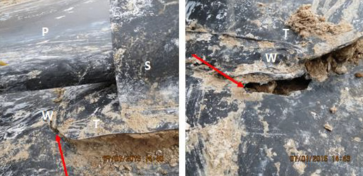
There were two more undesirable features of the pipe boots. Excessive wrinkling of the boot occurred along the pipe, and a neat fold/pleating effect of the excess skirt material was observed above the pipe. Since HDPE geomembranes are susceptible to stress cracking, project specifications usually require that the geomembrane be in intimate contact with the subgrade in order that it acts solely as a barrier and not as a load-bearing member of the lining system. Therefore, wrinkles and folds are most undesirable.
With this installation, several of the pipe boots had torn along the weld between the upper and lower parts of the boot under the pipe.
There were also tears in the liner at the corners of a patch to which a pipe strap was welded. Certainly the pipe needs to be restrained to prevent it moving and damaging the liner, but to do that by attaching it to the liner seems counterproductive. At the very least, the patch should have been welded to the liner around its full periphery, not just at the corners where the liner has been highly stressed.
There were two short cracks/tears along the edge of a patch extrusion weld at the toe of slope which when removed revealed a geocomposite vent strip to be full of sludge. The vent strips were unable to transmit gas.
The net result of the liner inspections was that there were many holes in the geomembrane liner through which water was leaking into the subgrade. The geocomposite vent strips became clogged with sludge and full of water, so they would not vent the biogas that continued to be generated under the liners. Whales formed.
Even though the geocomposite drain/vent strips were sloped towards a central drain, the system was again clogged which prevented venting of the gas.
Still, the second reactor appeared to be working satisfactorily, which may have reflected a lower, more manageable leakage rate. There was no guarantee that the second liner would not suffer whaling.
SOME SOLUTIONS
- As seen in this case and with a number of other anaerobic digesters, a grid pattern of geocomposite strips might not be effective in venting biogas from the leak detection system.
- Of course, it helps if the geomembrane can be installed such that it does not leak in the first place.
- Extrusion welds should not overheat the liner causing it to be locally oxidized and to be deformed with many stress concentrating notch geometries.
- All grinding marks/gouges should be covered by weld extrudate, and there should be no more than two welds in any one location.
- Use an experienced design engineer, an experienced liner installer, and a knowledgeable CQA firm.
- The final phase of CQA should be to perform a geoelectric integrity survey ( a leak location survey) on the liner to assure a minimum number of holes and cracks that might leak.
Remember, in anaerobic digesters, leaks often occur at pipe penetrations. As such, every effort should be made to avoid penetrations. If they cannot be avoided, they should be supported by concrete thrust blocks or something equivalent. There must be a means of removing leaked water very quickly and an effective venting system to remove any biogas generated under the liner.
**
Dr. Ian D. Peggs founded Geosynthetica in 1999. He led I-CORP International until his retirement from the company in early 2020. Dr. Peggs is one of the most prolific and influential figures in geosynthetics, particularly in regards containment design, forensic engineering on containment issues, and the advancement of new technologies to improve geosynthetics CQA. A previous version of this case study was published in the GeoAmericas 2016 Proceedings, which was published by Geosynthetica.


