
![]()
![]()
We thank Ian Peggs and Wendy Cortez of I-CORP International for orchestrating this transcript release and all affiliated permissions.
RELATED: EuroGeo 6 Geomembrane Panel Discussion Parts 3 – 5
VIDEO & PPT RESOURCES
- VIDEOS: The transcription is comprised of 5 recording parts (18 minutes each). All video files may be found on the EuroGeo 6 special session page. The time stamps included in this transcript are in accordance with the recordings.
- SESSION POWERPOINT: The presentation slides are available for download here (PPT – 22 MB file). Slide references in this transcript refer to this file. NOTE: Not all images from the presentation are included in this special publication on Geosynthetica.
GEOMEMBRANE WRINKLES, BRIDGING, BALLASTING, UPLIFT PANEL DISCUSSION, PART 1
Ian D. Peggs Introduction
(SEE: Video, Part 1)
Welcome to the panel discussion. I think we have something that is of interest to a lot of people. I want to begin a discussion on geomembrane wrinkles, bridging, uplift, and ballasting. I want to address the things that happen during installation of a lining system that may cause concern. How do we fix it or how to prevent these kinds of problems in the first place.
Panel members:
- Ian D. Peggs (I-CORP International, USA) – Moderator
- Paul Guinard (SOPREMA, France)
- Adnan Berkay Özdemir (Atarfil, Spain/Turkey)
- Michael Flynn (FLI Group, Ireland)
- Catrin Tarnowski (GSE, Germany)
- Richard Thiel (Thiel Engineering, USA)
PEGGS PRESENTATION:
THE ESSENTIAL QUESTIONS
How to prevent:
- Wrinkles on the floor
- Wrinkles falling down the slopes and collecting at the bottom
- Some ballasting between the wall and the slope below it
If it does happen, how do we resolve it and what do we do with it?
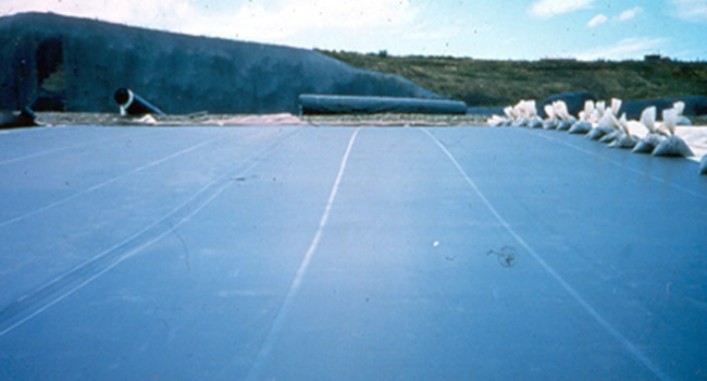
Wind uplift with no ballasting on an empty lining system causes uplifting of the lining. Wind uplift blows big wrinkles to one side of the pond depending on the predominant wind direction. We end up with big wrinkles along the toe of the slope with stress cracks going transversely across those wrinkles, not along the top as they usually do. How do we deal with it?
There is a little bit of bridging at the toe of the slope (Slide 7). How do we deal with that? Do we just put ballast and push it into the toe of the slope so that it is supported? Is it a concern? In the specifications, people ask for no bridging, but no bridging under what conditions? Does it matter what the temperature is in terms of bridging? Can we tolerate bridging in very low temperatures?
[00:09:10], VIDEO PART 1
FLYNN PRESENTATION:
AN INSTALLER’S PERSPECTIVE ON BRIDGING ISSUES
Main things to keep in mind (from an installer’s point of view):
- The geomembrane needs to be in a relaxed state all times. It is key that the geomembrane is sitting correctly.
- The interface between the vertical wall and the steep embankment slope is critical.
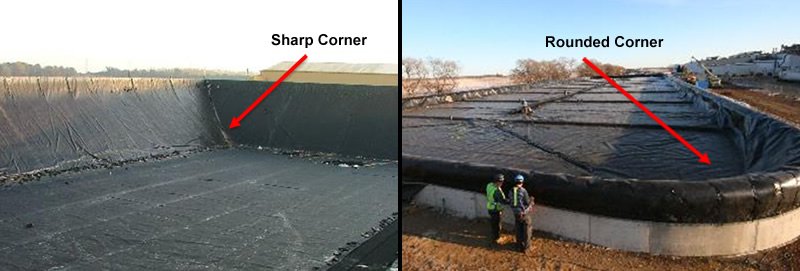
- Corners have to be sitting right; sharp or rounded that is a specific part of the design.
- The toe area has to be considered as an important area as to when to weld the toe area and how much of a toe runout there is to prevent to the buildup of wrinkles.
- Pipe penetrations are also another very important aspect of installation and care must be taken to prevent wrinkling.
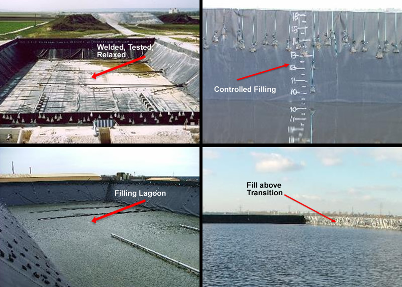
- Filling the Lagoon afterwards is also very important as to when to fill it and how to fill it.
- Permanent fixings
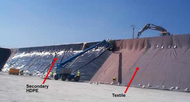
The arrows here (Slide 11) show various membranes in this lagoon. This project has a multi-layer lining system involved in this lagoon. This is a floating cover project. The ballasting of such a project during installation is extremely difficult because you have to ballast each geosynthetic layer in turn. You cannot allow the geotextile to slip while you are fixing the geomembrane. Holding each material in place during installation is very difficult. This takes a lot of thought, planning, experience and logistics in order to manage it successfully.
Both primary and secondary liners, drainage geonet and geotextile had to be left loose during construction. Movable ballast was adjusted to accommodate ambient temperatures so there is a whole host of different challenges involved with such an application.
In our experience it is easier to manage sharp corners as opposed to rounded ones. Rounded corners require more fixing and are more inclined to create wrinkles.
The ways to avoid wrinkles at the toe are to keep open toe seams, keep the liner relaxed and weld at the coolest time of the day. Moveable ballast is obviously the way to keep the toe in place before it is welded.
Other complicated parts of installation, in regards to bridging and wrinkling, are penetrations. Prefabricated penetration jackets are one way to overcome wrinkling and bridging.
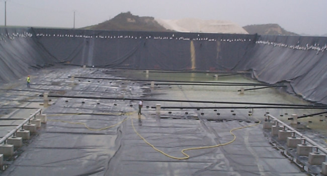
These photographs (SLIDE 15) show different elements of installations. Controlled, gradual filling helps to manage wrinkles and at the same time you are able to monitor and detect leaks in the base liner. Liner testing and monitoring should be done in a relaxed state.
[00:15:08], Video Part 1
OZDEMIR PRESENTATION:
WHAT MANUFACTURERS CAN DO
As a start-up, we are talking about professionalized installers. They are localized and it is conceivable that a manufacturer of geomembranes has little to teach to an installation company on many aspects related to the installation, so we have to trust their actions.
We as suppliers have some advantages since the majority of the information come to us and we have a huge network of installers from all over the world. All of this information flows to manufacturers and we can provide support for the installers.
The majority of the problems that we have talked about are caused from the crystallinity property of the geomembrane which is higher than 50%, in High Density Polyethylene (HDPE) geomembranes. Crystallinity provides to HDPE relevant chemical resistance and UV durability. In contrast it also has negative effects such as expansion and contraction.
Changes in temperature generate expansion and contraction. Consider a piece of material 100 linear meter length experiencing a temperature increase from 20 ° C, that is the ambient temperature within the factory, to 40 ° for example.
Expansion Δ=100 . 2,15.10-4.(40-20)= 0,43 m = 43 cm
Exposure of the geomembrane to UV radiation increases more or less the temperature depending on the color, black being the maximum absorption, over thermal gap on the ambient temperature. This affection sometimes justifies that temperature of the geomembrane surface is 70°C or even higher. With the example of the previous case, there would be an extra UV expansion which should be added to the previous one.
Extra UV expansion: Δ=100 . 2,15.10-4.(70-40)= 0,645 m = 64,5 cm
So, the total of the expansion of HDPE geomembrane in this case expected to be around
43 cm + 64,5 cm = 107,5 cm
NOTE: VIDEO FOR PART 1 ENDS HERE & RESUMES IN PART 2
VIDEO PART 2
Ozdemir presentation continues.
Expansion & Contraction of geomembrane cause wrinkles, raisings and terrain bridging from support.
It is logical to think that a wrinkle by expansion or a separation from the ground support will recover as soon as the temperature drops to the initial state. But, this is entirely not true.
What can we do about the treatment of these problems? As a rule, the criteria for a wrinkle is not to be higher than 60% of its width, starting from where obviously it separates from its support. The idea of this approach is that the wrinkle never has available excess material so that when the liner is put into service can not form a loop of material that could be pinched and so that plasticized for the weight of the content. There are methods to decrease the size of the wrinkle by using special geomembranes. Co-extruded light colored geomembranes can absorb less sunshine to help to reduce the surface temperature of the geomembrane. Sometimes the use of textured geomembranes by the bearing face, significantly increases the friction angle on this interface reducing wrinkles by introducing captive tensions which is not always good measure.
The wind is by far the biggest enemy of the installers.
Geosynthetics are usually lightweight products and wind generate suctions passing through inclined planes or elevations when it has the opportunity to enter under a geosynthetic. So, we talk about ballast against wind and within them, the provisional with bags during installation or the permanent one, with many other alternatives for the commissioning of the work.
It is very important to differentiate between ballast and anchorage, they are not the same.
A geomembrane anchor is the end finishing on the edge of it. A ballast is an extra weight that is placed along its route to avoid raisings. For this last reason a ballast must never entail the loss of continuity of a geomembrane.
A ballast is also a measure against wind and it will never serve to combat a wrinkle or a bridging.
The precautions are site specific.
Thanks for all his supports & mentoring, Mario Garcia Girones.
[00:03:34], Video Part 2
TARNOWSKI PRESENTATION:
BEST PRACTICES IN MANAGING WRINKLES & BRIDGING
I’m highlighting the issues from the perspective of a manufacturer and of an installation company.
We know about many cases reporting about dramatic wrinkling but there are also good experiences with flat lying HDPE-liners. The problem of thermal expansion, which is also dependent on crystallinity, exists, but you can still install the liner lying flat.
Wrinkling is dependent on the product itself, the installation technique, the design and the boundary conditions on the project. There are a lot of things to be considered to keep your geomembrane in the best position. For example, liners with textured surfaces might be more critical in regard to waves; waves once created may not go away on their own depending on the underlying material.
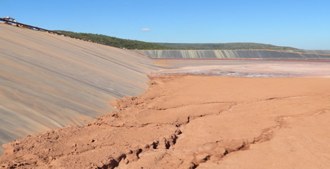
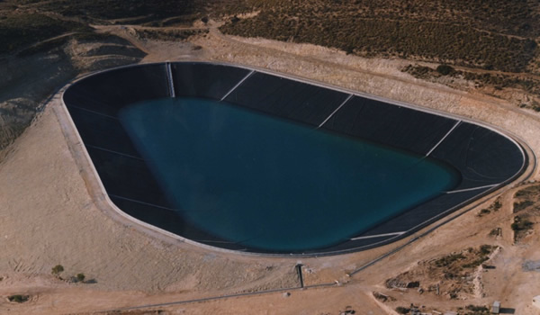
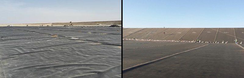
I want to present two pictures (SLIDE 32) showing that attempts to install a liner lying flat are not only made in Germany but in other countries as well.
The picture on the left is from Mauritania at noon and there are wrinkles, but they are not dramatic. The picture on the right is from Saudi Arabia and it shows good flat lying characteristics in the morning time. There is a third party controller on this project so there is strong focus on measures to keep it lying flat.
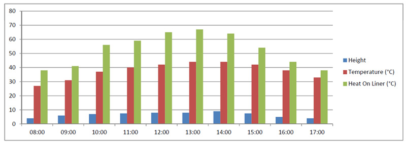
Recently we did research on waves created in projects in which black HDPE-liners were installed and high temperatures prevailed. As known, the temperature goes up to 70°, but there were no wrinkles higher than 10 cm at noon.
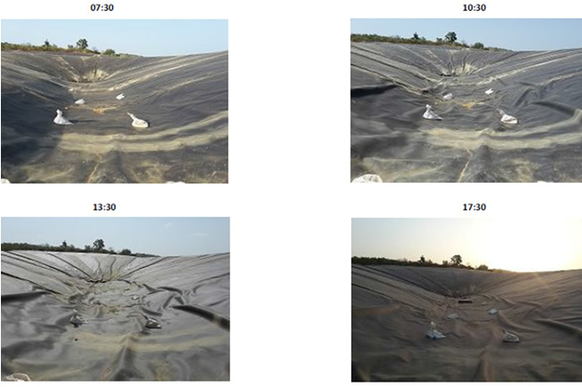
This picture (Slide 34) shows the development of wrinkles during the daytime. It is obvious that the wrinkles are critical on slopes and they have a tendency to creep along the slope and then to develop at the toe. Those wrinkles will stay in most cases so this has to be carefully considered during the design stage. The thermal expansion/contraction behavior of the material and the stress relaxation behavior also need to be taken into consideration. That is not only from the design point of view but also during operation of the project (as Michael showed very well with his research).
RELATED STORY: Best Practices for Minimizing Geomembrane Wrinkling
Wrinkling is critical in several ways. Big wrinkles can collapse, but also a small wrinkle can still be critical. Wrinkles are critical with regard to wind uplift. The more wrinkles you have, the more they will accumulate in the case of strong winds.
Bridging is the opposite problem but it is caused by the same phenomenon. The critical parameters are the height and length of the bridged liner, the prevailing temperature conditions, the method of placement of the top load and the liner performance itself. I would like to highlight, that areas where bridging is likely to occur should have few extrusion welds and careful consideration should be taken when cutting the bridged material and adding a patch by extrusion. This might add to a problematic case and not help. The same is valid for wrinkles – think carefully before cutting and adding extrusion welds.
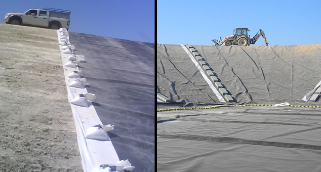
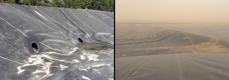
The design: Do we need intermediate anchors? How do we design a berm? How do we handle wind uplift design? In the left hand picture (Slide 36), it was requested that additional material be added since bridging problems occurred after installation. They considered cutting the material and installing another panel on the bottom area. When we visited to discuss this, there was a strong storm and you can see the wind uplift- so not the bridging a problem.
Designers should also consider how to do the penetrations.
The liner properties themselves are relevant to the creation of wrinkles. To my understanding, the thickness of the liner has no effect on the wrinkle height and how it occurs. Clearly, the thermal elongation behavior creates the effect. However, we never talk about the dimensional stability of the liner. If the liner has a good dimensional stability, it will keep more flat. Unfortunately you will not find a specification where a good dimensional stability is requested.
Light or bright colors help keep the liners flat during installation.
Then I would like to highlight installation principles, which help keep the liner flat.
It all starts with the storage of the material. In most cases the material is stored in an appropriate way. But, has the material been stored on a leveled area or was it e.g. kept on a wooden pallet? We also have to consider the temperature of the liner when it is unrolled.
One should also focus on the welding sequence of the material. Usually when panels are installed, one panel is welded to the other panel. It should be considered that all panels have the same temperature when being welded. This is the best practice. The panels should be welded only when they are lying flat.
Lying flat is achievable and is a team approach. It starts with the manufacturer, goes to the designer and installer, the installation control and ends at the operator. Wind uplift design needs to be considered for large uncovered areas and should not be left to the installer only.
[00:11:35], VIDEO PART 2
THIEL PRESENTATION:
BURYING WRINKLES – WHAT IS ALLOWED
I’m going to talk about what is allowed for burying wrinkles in large installations particularly for a heap leach pads or landfills.
My perspective is from the United States which I think applies to a large part of the world. This statement is what I call the high road and it’s in various publications in the United States. We all like statements like “The underlining geosynthetic material shall have all folds, wrinkles and other undulations removed before placement of the overliner on top of the geomembrane” or “the geomembrane must be flat when its backfilled” but to have these published at a high level is defeating our will because in fact it does not occur. It may occur in Germany which is great but if it doesn’t occur we have to get real with how we are actually going to deal with it.
We all know that waves and wrinkles are not good for any number of reasons like stress crack propagation, interference with drainage, poor intimate contact, potential for construction damage, high leakage rates, and they are bad when they coincide with GCL overlaps.
We also know that it is possible not to have wrinkles–Catrin promotes that–but the fact is that many projects around the world have wrinkles. Can we put a practical limit on this? Or should we go toward the extreme?
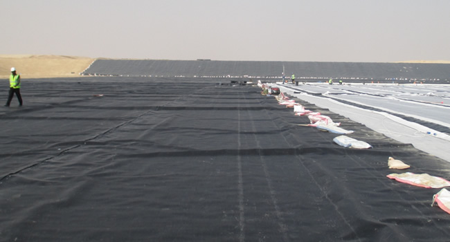
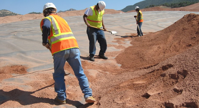
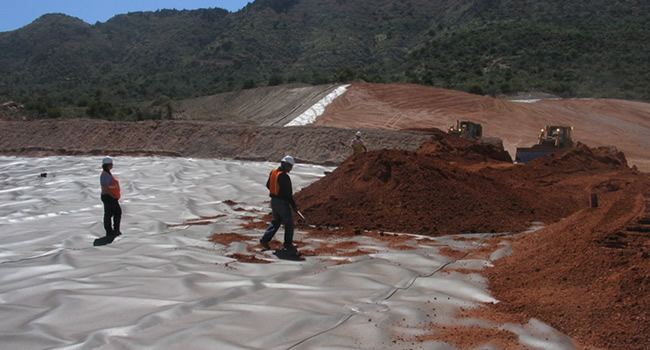
Here is a typical example (Slide 45) of an overliner being placed on a copper mine and there are wrinkles. The placement was stopped because the wrinkles were getting too large to cover.
In my designs I set a limit in my specifications that no wrinkle can be greater than 50 to 75 mm. When wrinkles get that big, I stop operation.
In this photo (Slide 47) there are people on the ground staying ahead of the wrinkles and they are ready to stop when the wrinkles get too big.
In the last two years, compliments to Doctor Kerry Rowe, there have been two studies done to corroborate my intuition of 50 to 75 mm. I am not saying it is the best answer but it feels correct. The first is this idea of the maximum interconnected wrinkle length to control leakage and the second one is the maximum unconfined GCL overlap width below a wrinkle to avoid excessive leakage.
In the first one Kerry Rowe’s group did a lot of studies showing that if you have a maximum interconnected wrinkle length of less than 200 m, it is a pretty good control of the worst case of leakage through a hole that might occur where there is a wrinkle. It just so happens that as you approach to 50 to 75 mm wrinkle height, that is about where this 200 m interconnected length occurs.
The second one was the GCL seam crossing. In the U.S. we use is 15 cm overlap typically but if there is a wrinkle coincident with a GCL overlap, which occurs very frequently by the way, there’s a potential for huge amounts of leakage so you want to ensure that the width of the wrinkle is less than the distance of the overlap. Again that 50 to 75 mm height is a very good starting point.
My conclusion is to stop the operation when wrinkles begin to approach that height. There are techniques to control wrinkles but that’s the “red line” in the sand.
[00:17:09], Video Part 2
GUINARD PRESENTATION:
CHOOSING THE RIGHT GEOMEMBRANE MATERIAL
I am here to show you the importance of choice of material. In France there are two main text on the subject, Fascicule 10 of CFG and Vademecum AFAG. In both of these texts there is no mention of wrinkles.
In these pictures (Slide 54) you could see different products being installed, black HDPE, reinforced PVC and FPO reinforced, green. All 3 have different wrinkling characteristics.
In France there are five different families of geomembranes. These products are bituminous materials, PVC-P, EPDM, and PP-F- and HDPE. (Speaker shows deformation characteristics of sample materials that he brought along.)
NOTE: VIDEO FOR PART 2 ENDS HERE & RESUMES IN PART 3:
EuroGeo 6 Geomembrane Panel Discussion Parts 3 – 5
REMINDER:
VIDEO & PPT RESOURCES
- VIDEOS: The transcription is comprised of 5 recording parts (18 minutes each). All video files may be found on the EuroGeo 6 special session page. The time stamps included in this transcript are in accordance with the recordings.
- SESSION POWERPOINT: The presentation slides are available for download here (PPT – 22 MB file). Slide references in this transcript refer to this file.


