By Chaido (Yuli) Doulala-Rigby and Martin Black – For a new major road construction (the Tinsley Link) in the North of England, a bridge approach embankment needed to be designed and constructed. A 500m-long mechanically stabilized earth (MSE) wall on piled foundations was proposed, one that would utilize geogrid reinforcement and enable the beneficial use of pulverized fuel ash (PFA).
The PFA—a waste product of pulverized fuel (typically coal) fired power stations—was supplied by the nearby EDF West Burton and Cottam power stations. The MSE walls were built up to 11m in height in order to achieve the required grade separation of the proposed link road alignment.
The project provides an exemplary case of geogrid design and construction.
REINFORCING TINSLEY LINK
Tinsley Link forms a key part of a government approved £28 million strategic Bus Rapid Transit (BRT) scheme in the North of England that aims to help unlock economic development in the Lower Don Valley by funding a high frequency bus service from Rotherham to Sheffield.
Sheffield City Council looked at various options of structures that could form Tinsley Link. The options included a continuous raised viaduct on piled piers, an embankment with piled reinforced concrete walls, and construction over a reinforced soil embankment. The geogrid-reinforced MSE option was selected due to advantages in cost, construction time, sustainability, and environmental friendliness.
The main role of geosynthetics in the work concern the construction of a bridge over existing rail tracks and the adjacent River Don—a section known as the Fitzwilliam Bridge—and the design and build of approximately 490m-long reinforced soil approach embankments to the bridge on a piled foundation.
PULVERIZED FUEL ASH FOR FILL
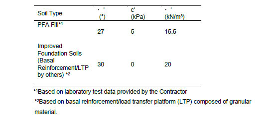
The existing founding soils were comprised of low-bearing foundation strata that would be unable to support the proposed reinforced soil embankments. The most cost-effective method of ground improvement was deemed to be a combination of Vibro Stone Columns (VSCs) under the lower parts of the wall and concrete piles under the higher parts of the wall. A geosynthetic-reinforced granular load transfer platform (LTP) on top would form the founding medium for the proposed reinforced soil embankment.
The reinforced fill needed to impose the lowest self-weight on the foundations. Three options were considered:
- Well-graded granular fill with maximum particle size of 125mm (such as type 6I/6J as per Series 600 of Highways Works Specification in the UK)
- Selected wet/stony cohesive fill ((such as type 7C/7D as per Series 600 of Highways Works Specification in the UK)
- Pulverized Fuel Ash (PFA)
PFA was selected due its low density, when compared to natural granular or cohesive fills. The supply came from coal-fired power stations located approximately 40 miles from the site.
Today, pulverized fuel ash is used widely as engineering fill and as a component for concrete. PFA normally undergoes a pozzolanic reaction and cements over time. When newly produced PFA is strongly alkaline; a pH as high as 11 is known, and >9 is normal but it does often decline in time towards the average value of 7. This high alkalinity excludes some materials (e.g., steel, polyester) from being used to reinforce PFA. This problem does not arise with high-density polyethylene uniaxial geogrids, as they are inert to chemical attach and are unaffected by high pH conditions.
TWO MSE SYSTEMS
Two types of MSE systems were used:
- Concrete modular face walls with PFA reinforced fill
- Steel mesh panel face thrust relief walls with PFA reinforced fill
The concrete modular face walls comprise four major components: concrete modular face block, HDPE uniaxial geogrid, polymeric mechanical block connector, and the reinforced pulverized fuel ash fill.
An added advantage of the modular block retaining system was that the individual component parts of the system could be easily transported to the site separately. In addition to that, the individual components are all dry laid so no curing time or formwork is necessary, saving precious time in the construction program.
The steel mesh panel face walls were comprised of uniaxial geogrid to reinforce the soil, steel mesh panel to provide retention to the slope face (also acting as formwork), and a layer of erosion control geotextiles, which provided a barrier to the vertical drainage layer that was placed in front of the reinforced fill.
MSE CONSTRUCTION
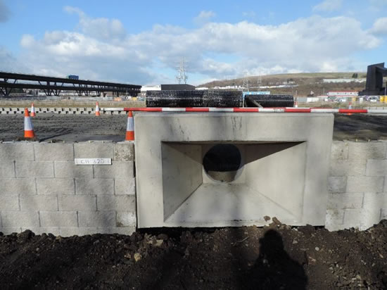
Construction with geogrid-reinforced retaining modular block or steel facing walls is a relatively straightforward procedure with all components dry laid, in accordance to a well-established and a tried and tested construction sequence. The pulverized fuel ash was compacted and reinforced with uniaxial geogrids.
The Tensar geogrid used on the project is characterized by long, slim apertures. In the manufacturing process, the high-density polyethylene grid is stretched in one direction to produce a geogrid with significantly higher strength in the direction of roll than in the cross direction. The geogrids are secured to the modular block facing by the polymer mechanical connector or through the steel mesh panel face secured with a horizontal steel rebar. The 200 mm wide, 200 mm deep, 400 mm long modular concrete blocks are laid dry without using mortar, removing the need for any water-based products to be used in the process. The grids are laid with the apertures perpendicular to the wall face blocks and slightly tensioned to remove any slack. PFA fill is then placed and compacted to 200 mm thickness, typically to 95% of its dry density. The geogrid is laid inbetween the compacted PFA fill layers at a vertical spacing typically varying from 200 mm to 600 mm.
For Tinsley Link a few extra construction measures had to be implemented in order to facilitate the successful installation of the PFA fill. PFA is susceptible to scour and washout. Additional drainage measures were made as outlined in BS8006-Part 1:2010 Cl. 6.10.5.2, Cl. 6.10.5.3, and Cl. 6.10.2.6.3. The whole PFA reinforced soil block was encased in drainage layers as follows:
- A 200mm thick drainage layer was placed over the entire base of all reinforced soil walls directly above the LTP.
- A vertical 300mm thick drainage sand layer of grading C or M (as defined in BS882) was placed directly behind the modular concrete blocks.
- A vertical 1000mm thick drainage sand layer of grading C or M (as defined in BS882) was placed directly behind the steel mesh facing thrust relief walls o behind both the bridge abutments.
- A 500mm well graded granular fill was placed at the crest of the reinforced soil walls below the finished pavement construction.
All drainage layers were constructed with adequate drainage pipes that were integrated and discharged off appropriately to the wider site drainage system.
Movement joints 20mm wide filled with compressible silicon joint sealant were constructed along the embankment where the foundation type changed from VSCs to PRIs and at the interface between the edge of the bridge abutment pile cap and the abutted remaining MSE walls.
A minimum 200mm void was allowed for in between the face of the steel mesh facing thrust relief wall and the bridge abutment to allow for any potential deformations of the TR2 face during its construction and to ensure that there will be no load transfer from the thrust relief wall onto the bridge abutment. This void can be filled with compressible material such as pea gravel or polystyrene blocks.
A number of sustainable urban drainage system (SUDS) drainage culverts, typically 600mm in diameter and animal passage tunnels were incorporated at set locations throughout the base of the embankment. Detailed geogrid arrangements were provided where the culverts and tunnels were interfering with the geogrids ensuring the stability of the MSE walls remained intact.
A SUSTAINABLE, AFFORDABLE SOLUTION
In the end, the savings of replacing the granular fill with pulverized fueld ash were in the order of tens of thousands of pounds. The benefit of using waste/marginal fill in the current economic and environmentally sensitive times was easy to demonstrate, thereby maximizing the role of geosynthetics in providing engineering solutions that are not only sustainable and environmental friendly but, above all, are structurally sound, aesthetically attractive, fast to construct, cost effective, and maintenance free.
Chaido (Yuli) Doulala-Rigby is Chief Civil Engineer with Tensar International Limited, United Kingdom. Martin Black is a Project Manager for Carillion Plc, United Kingdom.


