By John D. Herrmann, Bruce A. Lacina, P.E., and Stephan M. Gale, P.E. – In-place closure of coal combustion residual surface impoundments presents numerous challenges. Common methods of capping include placing 0.46 m (1.5 ft) of a compacted clay soil cap with an additional 0.15 m (0.5 ft) of vegetated cover. Geomembranes and geosynthetic clay liners are often considered as viable, cost-effective options to clay. A difficult and critical component of the design and construction is accounting for unsuitable soil conditions. Gaining equipment access to the site in order to install the clay cap or geosynthetic cover can prove extremely difficult.
Current methods of constructing a working platform include placing large quantities of aggregate or sand. Contractors have also experimented with chemical stabilization utilizing lime or cement. High-strength, woven geotextiles offer a safe, cost-effective, and thoroughly engineered solution. Geotextile benefits include separation of the structural fill from the weak subgrade soils, excellent filtration, confinement, and reinforcement.
Another benefit is the ability of geotextile rolls to be sewn into large panels. This process accomplishes two important goals:
- The engineered seam between adjacent geotextile panels is reviewed during the design process to ensure it meets the stability analysis target factors of safety.
- Deploying sewn geotextile panels can eliminate safety concerns related to accessing the soft, saturated impoundment soils.
CCR SURFACE IMPOUNDMENT PROJECT BACKGROUND
A large United States electric utility initiated the closure of a CCR surface impoundment in 2015. Engineering plans and specifications were created for the project and were subsequently bid by three general contractors. The impoundment was approximately 8.1 hectare (20 acre) with a depth of ash estimated at 9.1 m (30 ft). Project grading plans indicated a balanced site, with 50% cut and 50% fill. Fly ash from the cut areas was to be used as fill material. The final cap included 0.46 m (1.5 ft) of compacted clay and 0.15 m (0.5 ft) of vegetated cover.
THE CHALLENGE
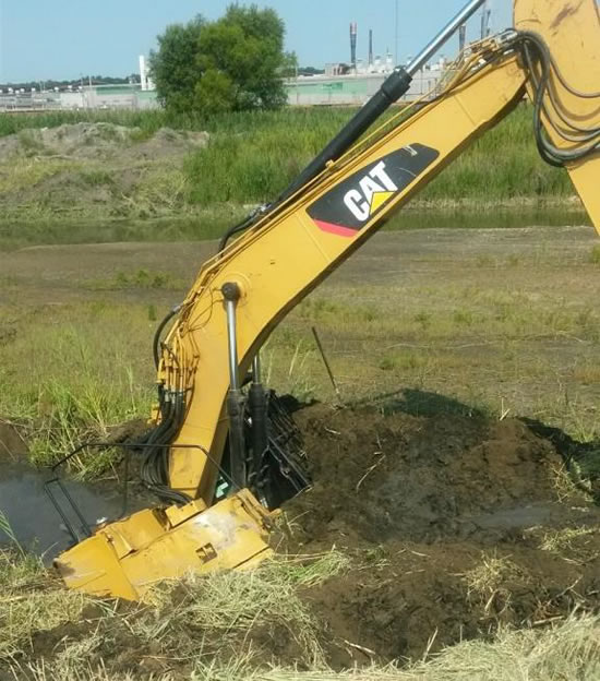
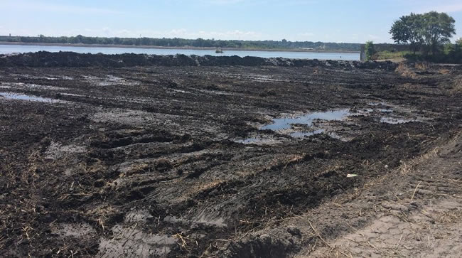
After reviewing the submitted bids, the utility awarded the project and a notice to proceed was issued. The contractor began clearing the existing vegetated cover. It was quickly discovered that soft, unsuitable subgrade conditions existed below the firm, dry crust. Fortunately, there were no injuries when the excavator broke through the crust and was nearly lost.
Following completion of clearing operations for areas without standing water, the contractor pumped any remaining surface water from the impoundment.
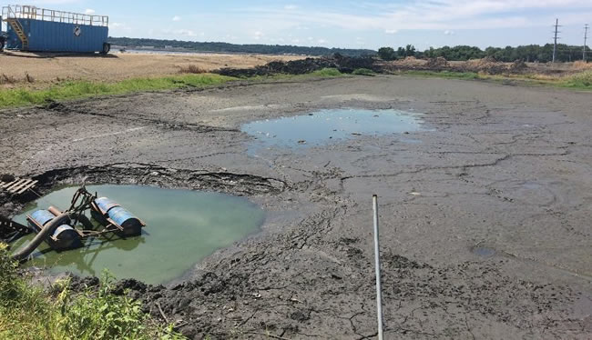
These activities made it apparent that reinforcement of the underlying soils would be necessary in order to complete the project safely and on time. The geosynthetic manufacturer met with the contractor onsite to describe the evolution of geosynthetic reinforcement materials for soft soil applications. A geosynthetic design alternative was prepared, one which would allow for the safe placement of both the fill material and compacted clay cap material.
CCR SURFACE IMPOUNDMENT REINFORCEMENT
Following the background presented regarding the evolution of reinforcement geosynthetics, the geosynthetic manufacturer prepared their recommended reinforcement solution to the contractor. Because a thorough soils investigation was not performed, several assumptions were made in the analysis and design stages.
A preliminary stability analysis was performed to assess geosynthetic reinforcement requirements for a cap consisting of a 1.83 m (6 ft) to 4.57 m (15 ft) of fill, 0.46 m (1.5 ft) compacted clay layer and a 0.15 m (0.5 ft) top erosion layer over the CCR material. The fill was modeled on a layer of high-strength, high-modulus geotextile to provide a construction platform for fill placement and to provide reinforcement for construction equipment traffic loading. The 4.57 m (15 ft) wide geotextile rolls were designed to be sewn together to provide the required level of reinforcement.

The soft CCR subgrade material was modeled in design based on a review of onsite construction videos, photos and moisture test results. A global stability analysis to access performance becomes appropriate when the CCR soils are soft with depth. Additional design protocols include reviewing surface stability concerns utilizing an unpaved design methodology. A unit weight of 1,602 kg/m3 (100 lbs/ft3) and an unconsolidated, undrained shear strength of 9.6 kPa (200 lbs/ft2) was assumed for the CCR material.
The analysis was completed using the computer program SlopeW by Geo-International. This program uses a two dimensional model. The Spencer method of slices was utilized, which satisfies both force and moment equilibrium. The program searches for critical failure surfaces. A sensitivity analysis was performed, which assumes the consolidated, drained CCR material would have a friction angle ranging from 27 to 37 degrees.
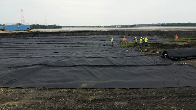
It was recommended that the geotextile be deployed in a sewn panel that is either fabricated on site and then pulled into place or sewn together at the project site. The fill was recommended to be placed and then spread in a direction which tensions the geotextile. If cracks or shifts occur during fill placement, then filling in that area should be stopped to allow the fly ash to settle and for excess pore pressures to dissipate. The analyses showed that pore pressure dissipation must occur in order for a consolidated fly ash friction angle to be achieved.
SURFACE IMPOUNDMENT CONSTRUCTION
Following a review of the proposed design recommendation by the contractor and owner, the geosynthetic manufacturer was authorized to proceed with manufacturing. The contractor decided to have the geosynthetic manufacturer sew panels in the factory rather than hire an installer to field sew the geotextile rolls. Panels were manufactured 22.9 m (75 ft) by 91.4 m (300 ft) and shipped to the jobsite. The contractor unrolled and deployed the panels over the impoundment. Fly ash fill was placed directly on the sewn, geotextile panel.
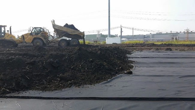
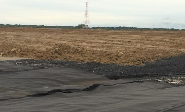
Fly ash fill placement proceeded quickly with no detrimental performance of the underlying subgrade. In cut areas, the geotextile panel was deployed and compacted clay was placed directly on top of the panel. The contractor quickly discovered that mud waves were forming in the CCR subgrade and construction was stopped. The geosynthetic manufacturer determined that pore water pressures were increasing in the subgrade, reducing shear strengths and causing mud waves. Although the geotextile material has a relatively high water flow rate and permittivity, dissipation of pore water pressure in the subgrade was limited by the relatively impervious clay material placed directly on top of the geotextile. The recommendation was made to add a geocomposite drainage layer directly on top of the geotextile to allow for better pore water dissipation.
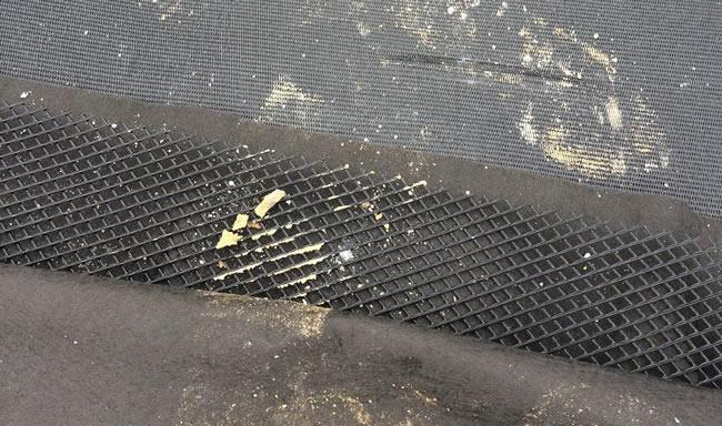
Once the geocomposite provided an avenue for dissipation of water coming from the CCR subgrade, the mud waves receded and construction resumed.
Thus, what started as a virtually impossible surface impoundment closure due to soft, saturated subgrade conditions ultimately became a relatively simple and on-time construction project. This project was completed ahead of schedule and under budget. The use of high strength, sewn geotextile panels proved to be a cost effective and safe alternative to traditional methods. The owner, engineering consultant, and contractor were so satisfied with this closure method that an additional CCR surface impoundment is now being closed with a similar geosynthetic reinforcement method.
RELATED: New Coal Ash Pond Capping Series from TenCate
GEOSYNTHETIC RESEARCH
Using geosynthetics to improve the performance of gravel surfaced roads and loading pads and for undercut and stabilization applications has been done in the United States since the 1970s. Much like today’s materials, early geosynthetics were either geogrids or woven or nonwoven geotextiles. Unlike today’s design methods, most of the benefit from the geosynthetic in early designs was attributed primarily to tensile membrane support. The tensile membrane support function relies mainly on the presence of a geosynthetic in the cross section and not as much on the reinforcement strength of the geosynthetic used. The geosynthetic design tools created during this time reflected these early tensile membrane concepts (e.g., Heukelom and Klomp 1962, Barenberg, et. al. 1975, Steward, et. al. 1977, Giroud and Noiray 1981).
Engineers, contractors, owners, and geosynthetic manufacturers have realized through continuous product development and improvement that newer geosynthetics with integrated mechanical properties can provide a measureable benefit over the earlier geosynthetics used in these applications. As a result, there are currently many more types and strengths of stabilization and reinforcement geosynthetics than were available in the 1970s. Modern design theories are able to incorporate the use of these newer geosynthetics when they have been properly calibrated to the performance of the material (Giroud and Han 2012).
Early geotextiles included 136 g/m2 and 271 g/m2 (4 and 8 oz/yd2) nonwovens and 890 N and 1.33 kN (200 and 300 lb) slit tape wovens. Nonwoven geotextiles were created to provide excellent separation, filtration, and drainage capacities. Newer geotextiles have been developed to fill demands created for better controlled filtration and drainage capacities and for higher reinforcement capacities, as well as the need for lower elongation under sustained loading conditions. High performance (HP) woven geotextiles were created to provide high tensile strength stabilization and reinforcement capacities. The newest RSi-Series roadway construction geosynthetics, for example, incorporate the improvements of more than forty years of product development and successful project histories.
HP woven stabilization and reinforcement geotextiles were first introduced in the 1980s and continue to be improved and refined. HP woven geotextiles have a long history of high performance and significant cost savings in subgrade stabilization and pond capping applications. Research into the functions and behaviors of these geosynthetics in these applications (Christopher and Lacina 2008) have led to the development of TenCate’s current Mirafi® RSi-Series and H2Ri stabilization/reinforcement geotextiles. These new geosynthetics have optimum integrated functions of layer separation, reinforcement strength, filtration and drainage capacity, and soil/aggregate interaction.
LABORATORY GEOSYNTHETIC TESTING
Both small-scale and large-scale laboratory testing have been performed over the years on geosynthetics to determine their relative performance and behaviors in different soil and gravel fills and under different loading conditions. Small-scale laboratory testing includes cyclic and monotonic pullout interaction, direct shear interaction, and filtration and drainage capacity. Large-scale laboratory testing includes the application of simulated wheel loads from truck traffic to compare, refine, and develop reinforcement/stabilization geosynthetics.
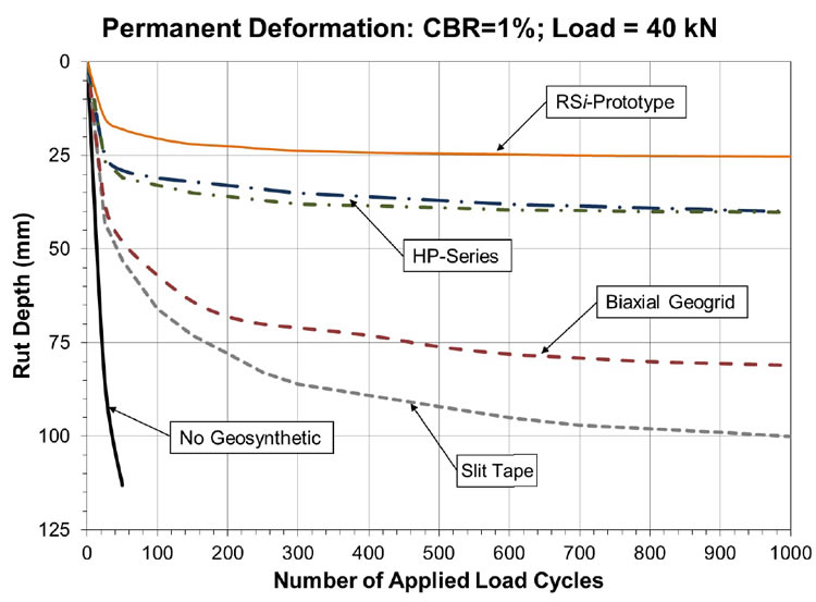
Test sections were constructed in a 2 m X 2 m (6.5 ft X 6.5 ft) X 1.5 m (5 ft) deep test box with removable facing that provided access to the interior. A 300 mm (12 in) diameter steel plate placed on a rubber pad was used to simulate wheel loads that provided a more uniform contact pressure on the test section surface. The applied loads and load frequency simulated a 40 kN (9 kip) wheel load or 80 kN (18 kip) axle load.
Another significant role geosynthetics contribute to subgrade stabilization is to quickly and efficiently dissipate pore pressures developed in the subgrade soil during dynamic loading.
The loading and data collection software were set up to provide a linear load increase from zero to 40 kN (9 kips) over a 0.3 second rise time, followed by a 0.2 second period where the load is held constant, followed by a load decrease to zero over a 0.3 second period and finally followed by a 0.5 second period of zero load before the load cycle is repeated, resulting in a load pulse frequency of 0.67 Hz. The maximum applied load of 40 kN (9 kips) resulted in a pavement pressure of 552 kPa (80 psi). This load represents one-half of an axle load from an equivalent single axle load (ESAL). The load frequency is selected to allow the data acquisition system time to store data before the next load pulse was applied.
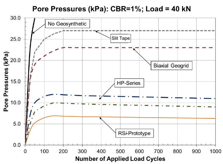
Large-scale lab testing of developmental RSi-Series geotextiles showed clear reductions in surface rutting behavior in large-scale testing compared to HP woven or slit tape woven geotextiles and geogrids. The RSi-Series geotextiles also provided better pore pressure dissipation during dynamic load testing and higher pullout resistance in common roadway geotechnical fills than previous woven stabilization/reinforcement geotextiles.
*
John D. Herrmann, AffM.ASCE and Bruce A. Lacina, P.E., M.ASCE work for TenCate Geosynthetics Americas. Stephan M. Gale, P.E., D.GE, F.ASCE is with Gale-Tec Engineering, Inc.
REFERNCES
Barenberg, E. J., et. al. (1975). “Evaluation of Soil Fabric-Aggregate Systems with Mirafi® 500X.” Civil Engineering Studies.
Christopher, B.R. and Lacina, B. (2008). “Roadway Subgrade Stabilization Study”, Proceedings of GeoAmericas 2008, Cancun, Mexico, International Geosynthetic Society, pp. 1013–1021.
Christopher, B. R., et. al. (2009). “Pore Water Pressure Influence on Geosynthetic Stabilized Subgrade Performance,” Proceedings, 2009 Geosynthetics Conference, Salt Lake City, Utah.
Giroud, J.P. and Han, J. (2012). “The Giroud and Han design method for geosynthetic-reinforced unpaved roads, Part 1: The method development and its calibration”, Geosynthetics, Vol. 30, No. 1, pp. 40-49.
Giroud, J. P.; Noiray, L. (1981). “Geotextile reinforced unpaved road design.” Journal of the Geotechnical Engineering Division, 107(GT9): 1233-1254.
Heukelom, W. and G. Klomp, A. J., (1962). “Dynamic testing as a means of controlling pavements during and after construction.” Proceeding of International Conference on the Structural Design of Asphalt Pavements, Ann Arbor, MI.
Koerner, R.M. (2013) “Carbon Footprint of Geosynthetics” Geosynthetics, October/November 2013, pg. 16.
Saghebfar, M., et. al. (2013). “Investigation of Bearing Capacity of Geotextile-Reinforced Paved Roads,” Mid-Continent Transportation Research Symposium, Ames, IA.
Steward, J. E.; et al. (1977). Guidelines for use of fabrics in construction of low volume roads.” FHWA-TS-78-205: U.S. Department of Agriculture, Forest Service, Pacific Northwest Region, Portland, OR.


