In-Situ Separation of GCL Panels Beneath Exposed Geomembranes
Summary
Geosynthetic clay liner (GCL) panel separation, when placed beneath an exposed geomembrane (GM), has occurred in at least five instances. Separation distances between adjacent panel edges are from 0 to 300 mm (0 to 12 in.), except in one extreme case where they were significantly larger. Taken collectively, the concern is such that an investigation has been undertaken. This White Paper presents the Geosynthetic Institute’s findings and subsequent position in this regard. Again it is emphasized that the geomembranes overlying the affected GCLs were exposed to the environment at all times; from the time of placement until the separation situation was observed (from 2 months to 5 years). The type of GCL panel separation described herein is not envisioned to occur for the more common situation where timely soil cover is placed over the GM/GCL composite liner.
After a brief introduction to the topic, the in-situ field occurrences of five GCL panel separation sites are described. Common characteristics of the available cases are listed and discussed. With this information as background, three causes of GCL panel separation are considered:
1. GCL shrinkage; perhaps accompanied by cyclic wetting and drying.
2. Longitudinal steep slope tensioning of the GCL.
3. GCL contraction on relatively flat slopes.
Within the above group and based on simulated laboratory studies; Item 1 is felt to be a contributing cause; Item 2 is felt to be the major cause; and Item 3 is a possible cause. These comments are made based on a number of investigations that have been undertaken and are presented herein, some of which are ongoing.
1. Shrinkage of GCL panels from their as-manufactured moisture condition to the dry state can be as high as 2.1% under laboratory testing conditions. The actual field mechanism of moisture uptake, and subsequent cyclic wetting and drying, however, is very complex and warrants additional study.
2. Longitudinal stressing of GCLs with subsequent transverse contraction (i.e., a Poisson’s Ratio effect, or “necking”) has been evaluated at laboratory scale and felt to be the major factor of panel separation when placed on steep slopes. This is particularly the situation for GCLs using double nonwoven geotextiles when neither are reinforced with an internal scrim.
3. Transverse contraction or “gathering” of GCLs should be investigated in the field since laboratory simulations are difficult to properly scale. The mechanism is believed to be
possible on relatively flat surfaces, but is felt to be less of an effect than the longitudinal stressing mentioned previously.4. GSI is actively pursuing the development of a nondestructive testing method (NDT) to detect GCL panel separation in the field without removal of the overlying geomembrane. Current efforts focus on the use of ultrasonics and ground-penetrating radar.
Within the context of these findings our recommendations are as follows:
1. Backfill the geomembrane/GCL composite liner in a timely manner (which greatly depends on site-specific ambient conditions), thereby preventing exposure and cyclic temperature extremes.
2. Use geotextiles to manufacture GCLs which minimize transverse contraction when they are longitudinally stressed, i.e., double nonwovens with no internal scrim are seen to be a major cause of the majority of the panel separation cases.
3. Increase the minimum installed overlap distance from the present minimum of 150 mm (6.0 in.) to the range of 250-450 mm (10-18 in.) to compensate for shrinkage and/or transverse shortening of the panels.
4. Control the as-manufactured moisture content of the bentonite component of the GCLs as low as possible to reduce possible field shrinkage.
5. For situations of exposed geomembranes, consider using insulation techniques such as thermal blankets, geofoam, or light colored geosynthetics (which may or may not be sacrificial) to minimize extreme temperature fluctuations.
We at the Geosynthetic Institute feel that the issue of in-situ panel separation of GCL panels beneath exposed geomembranes is presently understood as described in this White Paper. Conclusions as of the writing of this paper have been communicated to the GCL manufacturers and they are in the process of taking correction actions and of making products which will avoid the situation from occurring in the future.
Introduction
The idea of a composite liner consisting of a geomembrane placed directly upon a low permeability soil layer has been established since 1980 when both the United States and German Environmental Agencies embraced the concept. When the low permeability soil layer is a compacted clay liner (CCL), leakage rates from holes in the geomembrane (GM) are extremely low. This can be readily shown using Darcy’s formula wherein the area of flow is vastly reduced from the entire footprint of the containment facility to the actual area of the hole(s), Koerner (2005). This represents a reduction in flow rate of many orders of magnitude, hence the appeal of the composite GM/CCL system.
By 1985, initial trials of using a geosynthetic clay liner (GCL) as replacement for the CCL were attempted. After a very few years, GM/GCL composite liners became standard for primary liners in double-lined landfills. The validation of this particular strategy can readily be seen in the data of Figure 1 which plots average leakage rates from 287 double lined landfill cells. Here it is seen that by the time final cover is placed (Stage 3), the leakage rates from the GM/GCL composite primary liners outperform all other liners and are approaching zero. The numbers in parentheses are average values for the number of facilities indicated. This data set is felt by many to be extremely impressive for the use of GM/GCL composite liners and has encouraged such use in many other composite liner applications as well; for example,
(i) secondary liners in double-lined landfill systems,
(ii) single liner composite landfill systems,
(iii) final cover systems for landfills and waste piles,
(iv) liners for all types of surface impoundments,
(v) liners for all types of canals,
(vi) liners for earth and earth/rock dams and spillways,
(vii) secondary containment for underground storage tanks,
(viii) liners for heap leach pads
(ix) liners for agriculture and acquaculture
 |
| Figure 1 – Average leakage rates from 287 double lined landfills, Othman, et al. (1997). [Stage 1 – initial filling; Stage 2 – final filling; Stage 3 – after final cover is placed] |
In order to assure complete coverage of the unrolled GCL panels against the subgrade beneath them, standard manufacturing procedures print one or two continuous lines from the edges of the rolls as “overlap lines”. The distances that the overlap lines are from the edges varies among manufacturers but the minimum is
150 mm (6.0 in.). During field deployment one line or the other (depending on the direction of shingling) must be completely covered by the adjacent unrolled GCL panel. This installation technique is straightforward and is routinely accomplished. There is no necessity from a hydraulic perspective to physically or mechanically join adjacent roll edges, Daniel, et al. (1996). This procedure of overlapping the above amount is standard practice and embraced by CQC and CQA organizations alike. A minimum panel overlap along GCL longitudinal edges of 150 mm (6 in.) is recommended by the U.S. EPA in their technical guidance manual, Daniel and Koerner (1993).
The GCL Panel Separation Issue
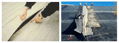
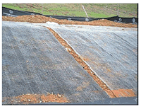
On at least five occasions, exposed geomembranes have been cut open for various reasons and the underlying GCL panels were seen to be physically separated from one another. As seen in Figure 2 the separation distances vary from negligible-to-300 mm (12 in.). It should be noted that in one instance (which will be described later) the separation distances were well beyond 300 mm (12 in.).
 |
|
| (a) Loss of initial overlap – no separation, hence, not included in Table 1 | (b) Separation of GCL panels ~ 200 mm (8 in.) (California, 2004) |
 |
| (c) Separation of GCL panels ~ 300 mm (12 in.) (Thiel and Richardson, 2005) |
Figure 2 – In-situ GCL panel separation at several field sites.
To say that such GCL panel separation is a concern is an understatement. The concept of composite action described in the introduction is greatly diminished under such circumstances. This White Paper is meant to acknowledge that the situation has occurred in several field circumstances, to investigate the probable causes, and to recommend materials and procedures to avoid its happening in the future.
Generalized Observations
The first field site where separation was observed was in 1993 at a Massachusetts power plant landfill near Boston. The occurrence was on a southerly facing side slope where the exposed geomembrane was removed (reason unknown) revealing GCL separation of approximately 300 mm (12 in.). The observers, Drs. David Daniel and Robert Koerner, discussed the situation and considered it an unknown anomaly. Since 2000, however, the situation has occurred in four other known situations.
In 2004, GSI was called regarding the situation at a landfill in California. The geomembrane had been exposed for approximately three years and was being backfilled with a soil operations layer that contained some large stones. Damage to the geomembrane was observed and in repairing it, the underlying GCL was found to have separated. Further examination at other locations at this site found GCL panel separations ranging from 60 to 450 mm (2.5 to 18 in.), with a gap of 1200 mm (47 in.) in one location. As shown in Figure 3, essentially every adjacent GCL panel along the upper southerly facing bench of the landfill slope had gaps exposing the underlying soil subgrade. The site required 265 m (870 ft) of GCL and geomembrane repair using cap strips along with subsequent CQC and CQA procedures. Clearly, this case heightened the concern over in-situ GCL panel separation and prompted this White Paper.
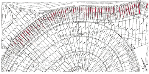 |
| Figure 3 – GCL gaps at California landfill. |
The common characteristics of the GCL panel separation case histories known to date by the authors are summarized in Table 1 and commented upon as follows:
|
Table 1 – Known Panel Separation Cases
|
|||||||
|
Date
(Duration of Exposure) |
Location
|
Slope
|
GCL Type
(geotextiles) |
Geotextile Orientation
|
Moisture
(%) |
Maximum Separation
|
Comment
|
|
1993
(5 yrs.) |
Massachusettes
|
2.5:1
|
Nonreinforced
(double woven) |
W-up
W-down |
|
300 mm
(12 in.) |
Toe Wave
|
|
2000
(5 mo.) |
Virginia
|
3:1
|
Reinforced
(double nonwoven) |
NW-up
NW-down |
24-31
|
300 mm
(12 in.) |
Slide
|
|
2001
(~ 15 mo.) |
Confidential
|
3:1
|
Reinforced
(nonwoven-woven) |
NW-up
W-down |
25-30
|
200 mm
(8 in.) |
Toe Wave
|
|
2004
(2 mo.) |
So. America
|
2º- 4º
|
Reinforced
(double nonwoven) |
NW-up
NW-down |
29-44
|
150 mm
(6 in.) |
Wet-Dry
|
|
2004
(3 yrs.) |
California
|
1.5:1
|
Reinforced
(double nonwoven) |
NW-up
NW-down |
25-29
|
1200 mm
(47 in.) |
Toe Wave
|
1. In all five cases, the GCLs were overlain by a geomembrane that was continually exposed to atmospheric conditions at the specific site.
2. The geomembranes were left exposed from two months-to-five years with no covering of any type.
3. The exposed geomembranes were textured on their lower surfaces which interfaced with the upper surfaces of the GCLs.
4. Four of the five cases had needlepunched nonwoven geotextiles (GT) as the cap fabrics of the GCL facing up against the overlying textured geomembranes.
5. Four of the five cases were on side slopes (generally facing south), the exception being one on the relatively flat base of a landfill.
6. Three of the four slope cases had evidence of geomembrane toe
waves at the base or bench of the slope involved. The relatively flat case had large standing waves in the geomembrane.7. The as-manufactured moisture content of the GCLs was 24% to 44% for four of the five cases. The Massachusetts site’s moisture content is unknown but estimated to be approximately 20%; the product has been subsequently depreciated by the manufacturer.
8. Three types of GCLs were involved:
• adhesive bonded nonreinforced GCL; woven GT up and similar woven GT down; this product is now depreciated (one case)
• needle punched reinforced GCL; nonwoven GT up and slit film woven GT down (one case)
• needle punched reinforced GCL; nonwoven GT up and nonwoven GT down (three cases)
9. The nonwoven geotextiles used in the manufacture of these GCLs were of the needlepunched type, but none had any type of woven “scrim” reinforcement, i.e., they were not composite geotextiles.
It is unknown if other GCL panel separation cases exist. If they do, it is unclear if they went undiscovered and were backfilled without notice, or were simply unreported and corrected by covering the separation area by a GCL cap strip.
Causes of GCL Panel Separation
This section discusses the probable causes of GCL panel separation based on the previous observations and subsequent laboratory investigations.
1. GCL Shrinkage; Perhaps Accompanied by Cyclic Wetting and Drying – The deployed GCLs were relatively high in as-manufactured moisture content, i.e., from 20% to 44%. This moisture, perhaps augmented by subgrade moisture uptake (Daniel, et al., 1993, Daniel and Scranton, 1996), under the exposed black geomembrane, rises to the underside of the geomembrane when exposed to sunlight. With the GM/GCL liner on a side slope, this moisture moves downgradient. If the geomembrane is not backfilled at the toe of the slope the moisture will continue under the geomembrane on the relatively flat portion of the facility. If the toe of the slope at the relatively flat portion of the facility is backfilled, however, the moisture will accumulate at the toe of the slope and create a longitudinal bubble, or “whale”, which did occur at three cases, recall Table 1. The net effect of the GCLs loss of moisture, however, will be shrinkage leading to loss of panel overlap.
Laboratory test data by separate laboratories have been accumulated and are presented in Figure 4 where it is seen that the maximum length change (i.e., shrinkage) is 2.1%. Recognize, however, that at 110°C both the bentonite and the geotextiles may be involved in the process. At 60°C, however, the shrinkage is probably due to the bentonite alone. For a typical GCL roll width of 4.4 m (14.5 feet) this represents a maximum overlap loss of 93 mm (3.6 in.). Thus, a physical separation of the adjacent GCL panels to the point where the underlying soil subgrade is exposed would not occur with an initial 150 mm (6.0 in.) overlap. Clearly, there is an additional mechanism(s) involved in these cases which is more serious than the GCL drying just described.
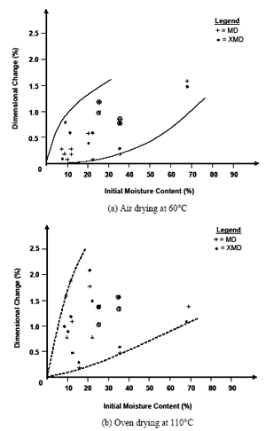 |
| Figure 4 – Dimensional shrinkage accompanying loss of as-manufactured GCL moisture content. |
2. Longitudinal Steep Slope Tensioning of the GCL – Along with the daily expansion and contraction of the exposed geomembrane comes a gradually downslope moving wave which accumulates at the toe of the slope. This was observed at three of the cases in Table 1 and is regularly observed in exposed reservoir liners, see Figure 5.
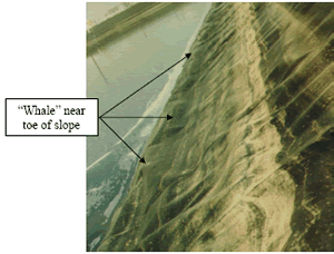 |
| Figure 5 – Horizontally oriented geomembrane wave in an exposed reservoir liner near the toe of slope. [This site did not have an underlying GCL and is only shown to illustrate the type of wave that exists in exposed geomembranes]. |
For textured geomembranes placed above GCLs which have an upper nonwoven needlepunched geotextile, a tensioning “drag” force can be mobilized. Assuming that the GCL remains in its anchor trench at the top of the slope, this action represents a full width panel tensile stress on the GCL. In so doing, a transverse panel necking (actually a Poisson’s Ratio effect) occurs.
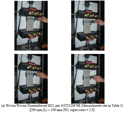
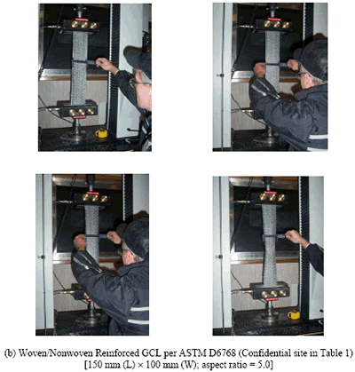
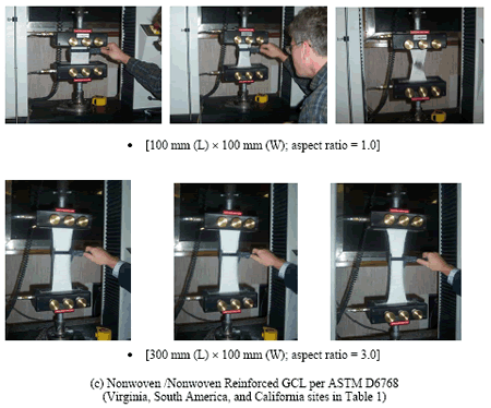
In order to investigate the magnitude of this effect a series of laboratory tests were conducted on the three different types of GCLs noted in Table 1. Figure 6(a) is the now depreciated nonreinforced GCL with identical woven geotextiles [slit film in machine direction (MD) and yarn in cross machine direction (XMD)] on opposite sides of the bentonite. Figure 6(b) is a reinforced GCL with a needlepunched nonwoven geotextile on one side and a woven slit film geotextile on the other. Figure 6(c) is a reinforced GCL with needlepunched nonwoven geotextiles on both sides of the bentonite. The individual specimens are characterized by their aspect ratio which is defined as the initial length between tensioning grips versus the specimen width. Aspect ratios are typically from 2 to 10 for field deployed GCL panels depending on the slope length.
Figure 6. Tensile tests on GCLs with accompanying measurements of transverse “necking”.
Figure 6. Tensile tests on GCLs with accompanying measurements of transverse “necking” (continued).
Figure 6. Tensile tests on GCLs with accompanying measurements of transverse “necking” (continued). In conducting many such tests with specimens of different aspect ratios on the three types of GCLs involved in these cases and plotting the results against the resulting transverse “necking”, a Poisson’s Ratio graph of each GCL type can be generated. Figure 7 shows this response according to ASTM D6768 testing for various lengths of test specimens as defined by their aspect ratio.
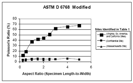 |
| Figure 7 – Results of tensile tests with measurement of transverse “necking”, aka Poisson’s Ratio, versus Aspect Ratio of original specimen length-to-width measurement. |
This important set of curves readily provides the necessary information and explanation into why the panel separation distances described in Table 1 are so large; particularly the California site which experienced, by far, the greates
t panel separation distances. Table 2 gives the requisite calculations based upon a GCL panel width of 4.4 m (14.5 ft). While the data speaks for itself, one can easily substantiate the magnitude of GCL panel separation distances in all of the cases (including the California site) under investigation.
| Table 2 – Calculations of GCL Panel Necking Based on ASTM D6768 Tension Testing |
 |
3. GCL Contraction on Relatively Flat Surfaces– Since all of the geomembranes were textured on their lower surfaces, an incremental so-called “hook-and-loop-effect” against the upper nonwoven geotextile of the GCL could occur in random orientations including transverse to the panel overlap. By cyclical expansion and contraction of the exposed geomembrane, the GCL may have been gathered beneath geomembrane waves (see Figure 8) during the warm part of the day and released during the cool night. This incremental gathering each 24-hour cycle may have caused the GCL to “bunch-up” within each panel losing a slight amount of overlap with each cycle. The cumulative effect could eventually cause some loss of overlap, which when combined with shrinkage, could cause GCL panel separation. While not felt to be the primary mechanism for GCL panel separation on steep slopes, it likely explains the one case (South America) where the GCL panels separated on a relatively flat surface.
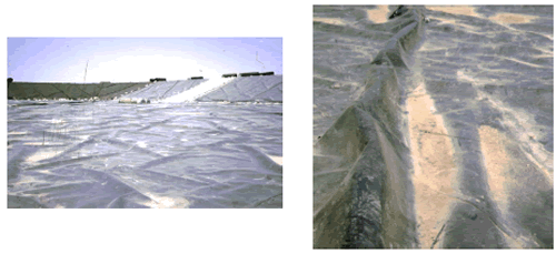 |
| Figure 8 – Waves in HDPE geomembrane on the relatively flat base of a landfill. |
In summarizing the three previously described likely causes of GCL panel separation we offer Table 3 for the range of movements that can be expected depending on the particular product used. It is offered under the assumptions that initial moisture contents of different GCLs vary, and that double nonwoven geotextiles are only used when they have a scrim reinforcement in one of the geotextiles. By so doing, the extreme movements seen at the California site are not possible and the two lower curves of Figure 7 are representative of future possible movements on steep slopes.
| Table 3 – Summary of GCL Panel Separation Causes |
 |
Recommendations
In counterpointing the field observations against the likely causes, some immediate recommendations and further action items are suggested to either avoid or mitigate the GCL field panel separation issue.
1. Do not leave GM/GCL composite liners exposed to the atmosphere. Soil backfilling with at least 300 mm (12 in.) of soil in a timely manner (which is very much site-specific) should be adequate in this regard. [This engenders other issues, such as cover soil stability, but they are site-specific design concerns, see Koerner and Soong (1998)].
2. Do not use GCLs with needlepunched nonwoven geotextiles on both sides unless one of the geotextiles is scrim reinforced. There are numerous possibilities in this regard, but all should have a woven component embedded within, or bonded to, the nonwoven component.
3. Increase the GCL overlap to compensate for the potential panel separation. With the exception of the California case, an increase of 100 mm (4 in.)-to-300 mm (12 in.) would have been adequate in the other cases. Thus, the overlap line printed on the GCLs during manufacturing should increase from the present minimum of 150 mm (6.0 in.), to between 250 mm (10 in.) and 450 mm (18 in.) depending on the GCL product used.
4. Protect the exposed GM/GCL composite during its exposure time by using thermal blankets, geofoam, or other insulation techniques.
5. Develop a NDT Method to Detect GCL Panel Separation – There are several nondestructive testing methods (NDT) available that might be used to investigate if GCL panel separation has occurred in the field, without physically removing the overlying geomembrane. GSI is currently investigating ground penetrating radar (GPR) and ultrasonic pulse-echo methods, Koerner, et al. (1984) and Koerner, et al. (1987), respectively. Both are based on sensing materials with different dielectric properties. As this research progresses, the results will be communicated accordingly.
6. Field Test Site – Lastly, it is possible to create full-scale field test sites to study the conditions under which GCL panel separation occurs. While this promises to be very expensive, the existence of the situation appears to warrant such an effort.
References
California (2004), Internal Report to Regional Water Quality Control Board.
Daniel, D. E. and Koerner, R. M. (1993), “Quality Assurance and Quality Control for Waste Containment Facilities,” U.S. EPA Technical Guidance Document, EPA/600/R-93/182, 305 pgs. (Also available from ASCE Press, Reston, VA).
Daniel, D. E. and Scranton, H. B. (1996), “Report of 1995 Workshop on Geosynthetic Clay Liners,” EPA/600/R-96/149, Appendix F.
Daniel, D. E., Shan, H.-Y. and Anderson, J. D. (1993), “Effects of Partial Wetting on the Performance of the Bentonite Component of a Geosynthetic Clay Liner,” Proc. Geosynthetics ’ 93, St. Paul, MN, IFAI, pp. 1483-1496.
Daniel, D. E., Trautwein, S. J. and Goswami, P. K. (1996), “Measurement of Hydraulic Properties of Geosynthetic Clay Liners Using a Flow Box,” Testing and Acceptance Criteria for Geosynthetic Clay Liners, ASTM STP 1308, Larry W. Well, Ed., American Society for Testing and Materials, W. Conshohocken, PA, pp. 196-207.
Koerner, G. R. and Koerner, R. M. (1995), “Temperature Behavior of Field Deployed HDPE Geomembranes,” Proc. Geosynthetics ’95, IFAI, Roseville, MN, pp. 921-937.
Koerner, R. M. (2005), Designing With Geosynthetics, Fifth Edition, Prentice Hall Publ. Co., Upper Saddle River, NJ, 799 pgs.
Koerner, R. M., Lord, A. E., Jr., Crawford, R. B. and Cadwallader, M. (1987), “Geomembrane Seam Inspection Using the Ultrasonic Method,” Proc. Geosynthetics ’87, IFAI, Roseville, MN, pp. 493-504.
Koerner, R. M., Lord, A. E., Jr. and Luciani, V. A. (1984) “A Detection and Monitoring Technique for Location of Geomembrane Leaks,” Intl. Conf. on Geomembranes, IFAI, Roseville, MN, pp. 379-384.
Koerner, R. M. and Soong, T.-Y. (1998), “Analysis and Design of Veneer Cover Soils,” Proc. 6th IGS Conf., IFAI, Roseville, MN, pp. 1-26.
Mitchell, J. K. (1976), Fundamentals of Soil Behavior, J. Wiley, NY, 422 pgs.
Othman, M. S., Bonaparte, R. and Gross, G. B. (1997), “Preliminary Results of Study of Composite Liner Field Per
