 By Giulia Lugli and Sachin Mandavkar – Soil can be stabilized by using a wide range of materials, such as cement, lime, and fly ash. When lime and water are mixed with a clay soil, modification of the soil properties and stabilization reactions begin. In highly alkaline environments (pH >12 for a short period of time), this can cause corrosion of steel elements in an engineered reinforcement system, such as with mechanically stabilized earth walls. LLDPE-coated, planar, high tenacity polyester strips used in the reinforcement of concrete facing panels of an MSE wall in these environments provide a strong solution.
Properly using this approach requires an understanding of the soil parameters, lime percentage in the reinforced backfill, the behavior and the durability of the LLDPE coated reinforcement, and the installation procedure.
IMPROVING BACKFILL MATERIALS
The interaction between backfill material and reinforcing elements plays a significant role in the performance of MSE walls. The backfill is usually reasonably free from organic or other deleterious materials and conforms to applicable gradation requirements. Where its suitable to a design, the use of onsite material may be preferred in order to reduce the overall cost of a structure.
Clay of moderate to high plasticity or fine-grained soils for backfill require the improvement of the soil parameters. This process will reduce settlement, increase bearing resistance, and improve the overall stability of the structure. The type of soil improvement (stabilization) is classified based upon structural performance criteria in three main categories:
- Unbound materials – Resistance is mainly provided by cohesion and friction between the particles and no significant tensile strength is shown. Deformation is given by shear, densification and breakdown of particles
- Modified materials – A small amount of a stabilizing agent is added to an unbound material to increase the strength or reduce the moisture or frost susceptibility without increasing the stiffness
- Bound materials – A stabilizing agent is added to an unbound material in order to obtain better structural performances. The resulting material has a new developed shear strength given by particle interlock, chemical bonding and cohesion, and significant tensile strength. Deformations are due to cracking through shrinkage, fatigue, and overstressing.
The choice of the stabilizer may be determined factors such as gradation, plasticity index, climate, availability and cost of the material, construction equipment availability, experience of site labor, etc. Particle size distribution and Atterberg limits are often considered in order to get a preliminary idea of the best type of stabilization. All materials must be properly assessed and thoroughly evaluated in a certified laboratory before any fieldwork starts, in order to estimate their uniformity and quality.
LIME-STABILIZED BACKFILL
Lime treatment can chemically transform unstable soils into exploitable materials, improving both workability and strength. Small amounts can be used to dry and modify soils to create temporary roads and working platforms. Larger amounts can result in a permanent structural stabilization of soils. Lime can stabilize soils under the form of quicklime (calcium oxide – CaO), hydrated lime (calcium hydroxide – Ca[OH]2), or lime slurry. Quicklime is manufactured through the chemical transformation of calcium carbonate (limestone – CaCO3) into calcium oxide. Hydrated lime is produced by making quicklime chemically react with water.
When lime and water are mixed with a clay soil, these chemical reactions occur almost immediately:
Soil drying: quicklime immediately chemically combines with water and starts releasing heat. The water present in the soil reacts, and the generated heat evaporates some additional moisture leading to soil drying. The resulting hydrated lime will then react with clay particles reducing the soil capacity to hold water (additional drying). Drying occurs quickly, within a matter of hours, enabling the contractor to compact the soil much more rapidly than by waiting for the soil to dry through natural evaporation. In case of hydrated lime or hydrated lime slurry, only drying due to reaction with clay occurs.
Modification: After the initial phase, the calcium ions (Ca++) from hydrated lime move onto the clay particles displacing water and other ions. The PI of the soil dramatically decreases as a consequence in a process called “flocculation and agglomeration” that occurs in a matter of hours, and so does its tendency to swell and shrink. The soil becomes easier to work and compact.
Stabilization: Long-term strengthening is due to pozzolanic reactions that occurs in the highly alkaline environment (pH >12 for a short period of time), which leads to the breaking down of the clay particles, and allows the formation of calcium silicates and aluminates that form the matrix that contributes to the strength of lime-stabilized soil layers. The soil is thus transformed: the clay surface mineralogy is altered producing a hard, relatively impermeable layer with significant load bearing capacity. The process begins within hours but is relatively slow and can last for years. Warm weather is generally required for the process: the air temperature should be approximately 5 °C rising during the reaction. Colder weather conditions are possible if lime reaction is used for drying wet soil. Frozen soil condition should be avoided or treated properly following specific procedure.
In general, fine-grained clay soils (with a minimum of 25% passing the #200 sieve and a plasticity index greater than 10) are considered to be suitable for lime stabilization. Clay components in the soil are required in order to react with lime, as lime stabilization technique requires a soil that contains natural pozzolan.
GEOSTRIP REINFORCEMENTS IN HIGHLY ALKALINE ENVIRONMENTS
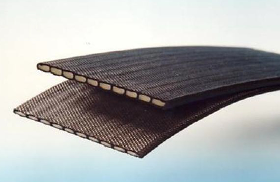
The choice of the proper reinforcement is fundamental in the design with lime-stabilized soil. If the corrosion penetration occurs, the design life of the structure may reduce considerably. The Maccaferri MacRes® MSE System combines the precast facing panels with high tenacity polyester strips co-extruded with LLDPE (Linear Low Density Polyethylene).
Resistance to chemical degradation of the polyester strips is generally a function of the following index properties:
- PET Molecular Weight (Mn)
- PET Carboxyl End Group Content (CEG)
- PET retained strength after 500 hrs in weatherometer
Biological degradation is also function of the Molecular Weight. As per FHWA–NHI–00-044 polymers with high molecular weight are less susceptible to the enzymatic degradation.
The polyethylene sheath represents an additional protection to the polyester yarns from the aggressive backfill materials. In general, the most chemically aggressive backfill materials are usually of fine particle sizes (e.g., clayey sand or sandy clay soils) which may cause little or no damage to the polyethylene sheath. The durability reduction factor values, RFD, depend on the soil pH and on the design temperature of the soil. Usually RFD is provided for pH range between 4.5 and 9 and between 9 and 11.
At pH levels greater than 10, and over long-term durations at pH >9, the surface of polyester fibers is progressively eroded by “external hydrolysis”. This leads directly to a loss of strength and occurs in parallel with internal hydrolysis. For this reason, there are restrictions on the use of polyester (PET) in environments of pH 9 and above, although these effects have so far been observed at higher pH values, which occur very rarely in natural soils.
Greenwood’s research (2007) indicated a high level of chemical resistance in geostrips due to the presence of the protective sheath. Still, where the pH is likely to exceed 9.0 in the long term, an assessment should be performed for the exact environment (pH, type of metallic ion, temperature).
PROJECT: MSE WALL WITH LIME-STABILIZED BACKFILL
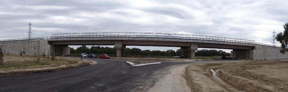
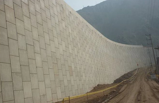
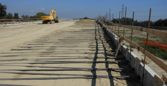
During the construction of a new ring road system in Tangenziale di Forlí, Italy, about 4,700 m2 of retaining walls with concrete facing panels were realized over a mainly cohesive alluvial soil with compressible sandy silt and clay with sand and gravel stretches. These soils were subject to significant geotechnical problems, especially related to both differential and total settlements. The MSE structures, which included nine wing walls, were realized with polyester strips as the reinforcing elements and square 1.5 x 1.5 m concrete facing panels.
The reinforcing strips used for this project varied from a minimum ultimate tensile strength of 27 kN to a maximum of 36 kN. The maximum height of the MSE wall was about 8.5 m and the vertical spacing between each reinforcement layer was 0.75 m.
The soil used for the construction of the embankment originally came from the excavation of a subway belonging to the same lot. This was determined to be the most suitable choice from cost and sustainability perspectives. However, the silty clay nature of the material was not truly suitable for road construction.
A soil stabilization technique had to be used to enhance the soils characteristics.
After careful design and testing, lime stabilization was adopted. (Lime was the 2.5% of the soil weight.) The soil-lime mix, respecting the planned amounts of lime, took place outside of the field test, and the treated soil was transferred and compacted on site. The resulting material had an improved shear strength—provided by particle interlock, chemical bonding, and cohesion—and significant tensile strength.
Typical values for mechanical resistance of lime stabilized soils are c’=25 kPa and f’=30 °.
For this project, the mechanical resistance values were obtained by laboratory testing to characterize the lime-stabilized soils cohesion, unit weight and friction angle. In this case a cohesion c’ equal to 0 was assumed, per client request.
Giulia Lugli is EMEA Region, USA & Canada Maccaferri Vertical Walls Sector Technical Specialist and Sachin Mandavkar a Technical Manager for Maccaferri Inc. (USA), www.maccaferri.com
A longer version of this article was published in the GeoAmericas 2016 proceedings along with 200 other geosynthetics technical papers and lectures. The proceedings are available for purchase and download at www.geoamericas2016.org.
REFERENCES
BBA Certificate n. 12/H191, (2012). Linear composites retaining walls and bridge abutments systems – ParaWeb™ straps for reinforced soil retaining walls and bridge abutments.
Hicks, R. G. (2002). Alaska Soil Stabilization Design Guide.
Misano, V. (2006). Il trattamento dei terreni nella costruzione delle linee ferroviarie ad alta velocità/capacità.
Washington State department of Transportation (2012). Geotechnical Design Manual.
National Lime Association (2004). Lime-Treated Soil Construction Manual.
Burgoyne C, Merii A. L. (1993). Hydrolysis tests on polyester yarns. Report CUED/D Struct/TR 138, Engineering Department, University of Cambridge, UK.
McCreath M. K., Balderson T. J. (1999). ParaWeb 2S – the effect of an alkaline environment on tensile strength, University of Cambridge.
Elias V., Salman A., Goulias D. (1988). The effect of pH, resin properties and manufacturing process on laboratory degradation of polyester geotextiles. Geosynthetics International, Vol. 5, pp 459-489.
Greenwood J. H., Trubiroha P., Schröder H. F., Franke P., Hufenus R. (1996). Durability standards for geosynthetics: the tests for weathering and biological resistance. Geosynthetics: Applications, Design and Construction; ed. De Groot MB , den Hoedt G, Termaat R. Balkema, Rotterdam, pp637-642.
Naughton, P.J., Balderson,T. & Lozano (2005). The properties of polyethylene encased high tenacity linear elements. Geosynthetics and Geosynthetic-Engineered Soil Structures: Contributions from the Symposium Honoring Prof. Robert M. Koerner, Ed. Ling, H.I., Kaliakin, V.N., and Leshchinsky, D., pp 19-38.
Schmidt H. M., Te Pas F. W. T., Risseeuw P., Voskamp V. (1994). The hydrolytic stability of PET yarns under medium alkaline conditions. 5th International Conference on Geotextiles, Geomembranes and Related Products, Singapore. International Geotextile Society, 1994, pp 1153-1158.
Schröder H. F., Bahr H., Kneip G., Lorenz E., Schmücking I., Seifert I. (2000). Long-term resistance of PET geofibers to inner and outer hydrolysis. 2000 China International Nonwovens/Techtextiles Conference, Beijing, China, pp165-183.
NTPEP Report No. 8508.1 (2010). Final product qualification report for linear composites Paraweb/Paralink and Paragrid product lines.
BTTG Report 12462A/HPM005 (2003), Manchester, England.
Greenwood J. H. (2007). Assessment of ParaWeb, ParaGrid and ParaLink to ISO TR 20432, Report Number: 2007-0242 Issue 5.
Boyle G. (1995). Behaviour of ParaWeb in strong acid or strong alkali and Resistance of ParaWeb to strong acid or strong alkali.


