In 2016, Geosynthetica had the honor of managing the GeoAmericas 2016 conference and publishing the proceedings. GeoAmericas 2020 will soon take place in Brazil. As part of a series leading up to that event, Geosynthetica is publishing some of the field contributions to the 2016 event. Here, we look at at a unique oil terminal modernization project that utilized concrete-filled geotextile tubes. The custom-made geotextile tube design along with the construction procedure allowed significant savings in time and logistical resources, additionally demonstrated to be the solution that adjusted better to the particular conditions without interrupting the operation of the oil terminal. The article comes from work by Angel H. Díaz Jr. (Geomembranas y Geosintéticos SA de CV) and Christopher Timpson (formerly of TenCate Geosynthetics).
1. THE OIL TERMINAL
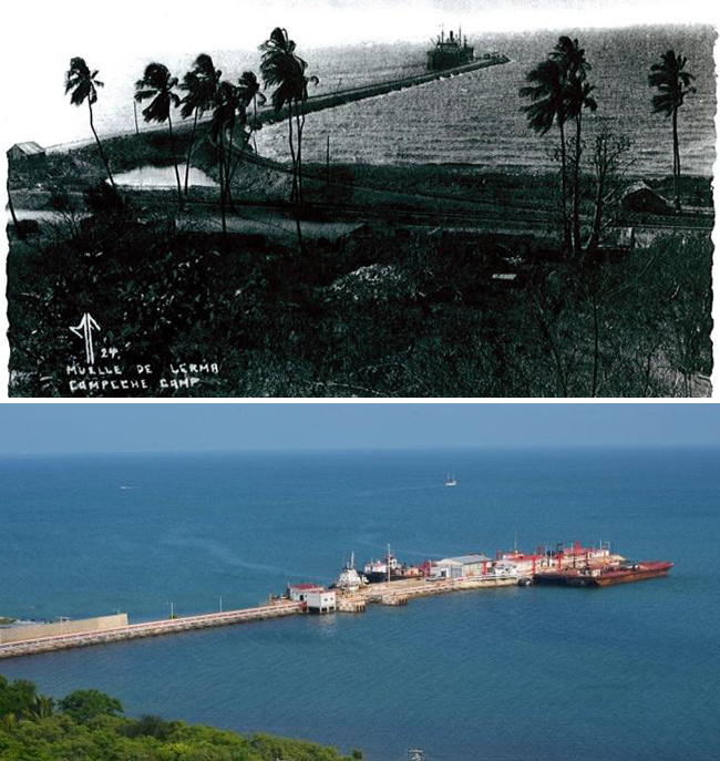
The oil terminal in Lerma, Campeche, also known as Castillo Breton Dock, that is currently operated by PEMEX, the Mexican state-owned petroleum company, is a key marine infrastructure facility for the provision and distribution of petroleum products (gasoline, diesel, marine diesel and fuel oil) in the States of Campeche, Quintana Roo, and for the entire Yucatan peninsula in terms of fuel oil for electric power generation.
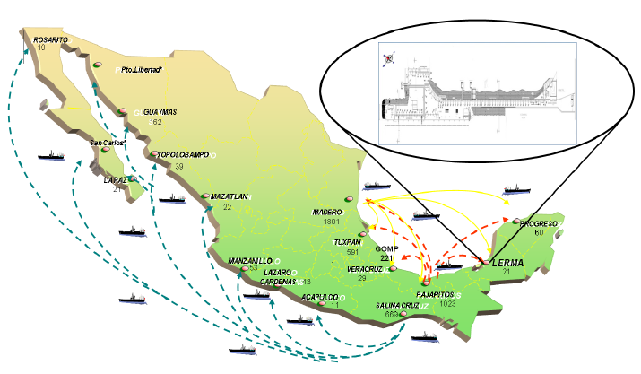
This Oil terminal, built in 1946, has a 507m length dock, 7,663m2 area and three discharge stations. The modernization and protection of the installations will allow extending the lifetime of the infrastructure, fulfilling the international security and environmental protection standards, assuring its operation in the future.
The petroleum products are received via tankship and barges from the Marine Terminals of the Gulf Coast making their transfers directly from the dock to the distribution and storage terminal of Campeche, using two pipelines of 12” diameter for fuel oil, three pipelines of 8” diameter for gasolines and one pipeline of 8″ diameter for diesel; all in a length of about 890 m.
The engineering challenge at the job site was to perform all the works without stopping the operation of the facility, especially for rebuilding the slopes of the dock nearby to the pipe lines installation. Due to natural wave erosion the rock protection of the dock slopes was reduced, needing to be reinforced. Different alternatives were considered: rock, concrete cubes, gabions, and geotextile tubes. After an intense technical, installation procedure and cost evaluation, concrete filled geotextile tubes were selected as the solution for reconstructing the slopes of the dock.
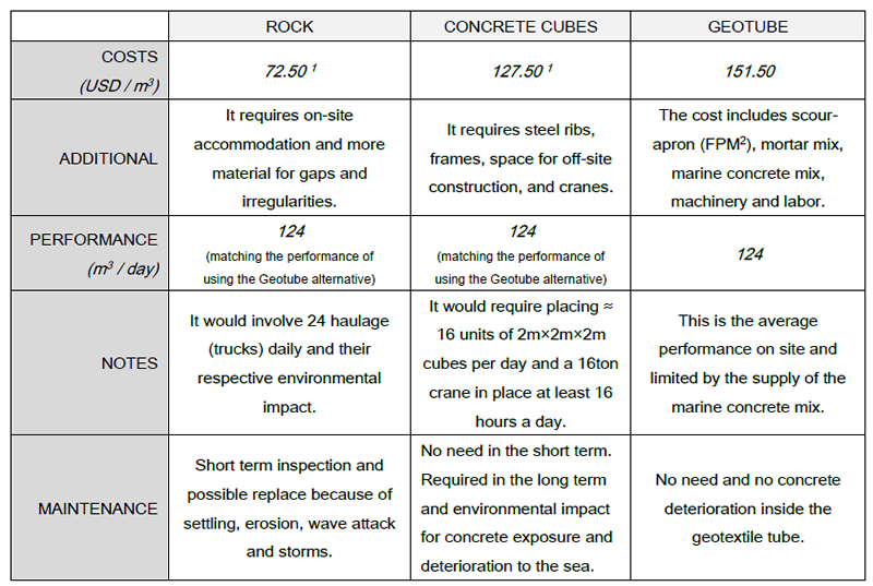
1 Cost includes only m3 of rock supply on site and m3 of concrete supply on site, this cost needs to consider additional cost of materials, machinery, equipment and labor
2 Filter Point Mattress
The engineering design for these geotextile tubes considered numerous conditions, being the most relevant: heavy enough gravity structures for resisting the wave action, a size able to be filled in one maneuver according to the existing marine concrete supply on site, the capability of installation of the structures emerged and submerged, and confinement of fine concrete particles preventing environmental impact on the surrounding natural environment.
In Mexico this solution stands as an innovation on the usage of geosynthetics and concrete, combining them for having massive units for construction, flexible formwork (tailor-made), less environmental impact construction method, heavy-duty structures, filled in place with minimum equipment and need of space.
RELATED: PVDs for Soil Improvement: Projects in Egypt and Mexico
2. THE CHALLENGE OF HISTORY
With more than 50 years with almost no major modernization and rehabilitation of the installations of the oil terminal, the modernization project included works form the range of civil, mechanical, electric and instrumentation equipment; all of them at the same time. The organization and speed was critical, so that the different works performed should be developed in the same limited space during the operation and arrival of barges. At that time, the dock had only one access lane to get in and go out, all the contractor machinery, workers, material supply and the dock employees must had to coordinate very well keeping the safety standards on this kind of facilities. For the scope of this paper the design and installation of the geotextile tubes will be the main topic.
After a numerous exchange of blueprints, technical information and background information of the technology of geotextile tubes applied in Mexico the Mexican state-owned petroleum company completed the authorization to begin the work on site. For this project and for the company it was greatly estimated that the geotextile tube technology was cost efficient, provided high durability, would be easy installed and is highly flexible. This technology has been proven in installations in more than 50 countries; it also has been used over 50 years around the world and more than 10 years in large projects in Mexico.
The terminal has over 500 m of dock slopes exposed to waves and sea erosion. The existing rocky slopes were under erosion had also destabilizing. The protection of these slopes includes placing 2,500m of geotextile tubes in three berms from the foot of the slope to the height of the dock roads and the other infrastructure inside.
The protection technology of geotextile tubes filled with concrete will control the erosion and the undermining that occurred on these slopes affecting the operation in the terminal. Geotextile tube units will receive the wave impacts, diminishing the force of the sea to the dock. In addition these structures for the protection zone and formation of slopes come to have greater weight than the existing rock and also more than the concrete cube proposed; the estimated weight of the designed geotextile tubes were 35ton, being filled and installed on site avoiding the complex task of carrying materials to work and placing them next to the pipelines.
3. MASTER PLAN, CONSTRUCTION PROCEDURE & GEOTEXTILE TUBE DESIGN
The slopes of the dock were severely eroded, so the first action was to build a three berm structure with the existing rock on the slope. Once the slope with its three berms built, a scour-apron was placed on the surface with two purposes: first, to have a scour protection preventing undermining at the foot of the slope; and second, to have a support surface and a contact puncture protection between the rocks and the geotextile tubes. In this case the scour apron selected was a concrete mattress, a filter point mattress (FPM). On those new berms created on both sides of the dock the geotextile tubes will be placed submerged and emerged to create the slope protection.
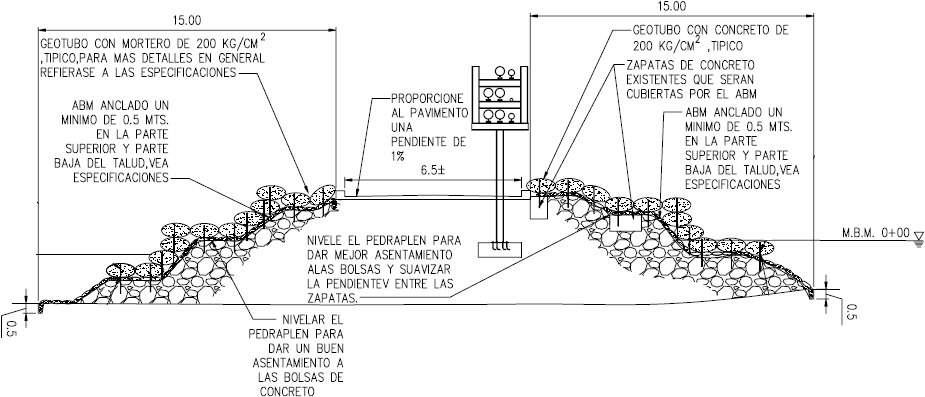
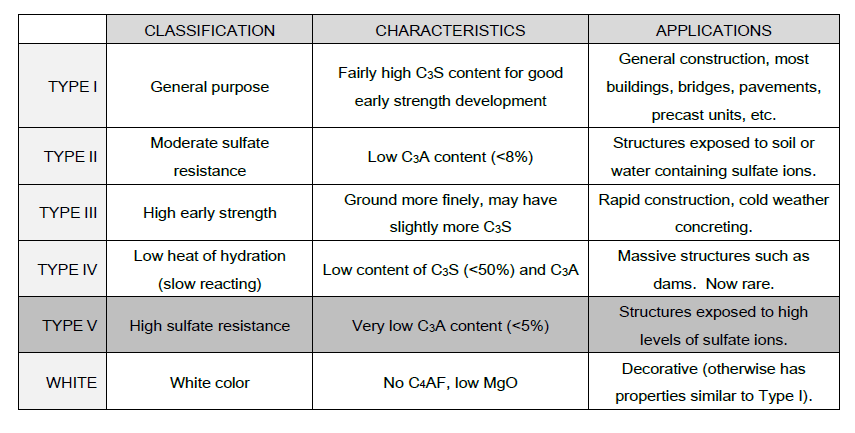
The concrete mix selected for the filling of the filter point mattress and the geotextile tubes was a marine concrete Type V with a compressive strength of f’c= 200 kg/cm2. This kind of concrete is used when a high sulfate resistance is essential, and generally gains strength more slowly than Type I.
The supply was arranged weekly with the concrete supplier in concrete mixer trucks and to be discharged directly from it to the geotextile tubes, pumped by its high range hosing system.
MORE GEOAMERICAS: Long-Term Outdoor Exposure Testing of Geosynthetics
This benefit of the concrete mixer truck hosing system and that the geotextile tubes could be basically plugged in to it and filled was a key advantage in the logistics involved during the whole project and most important for keep working with the pipelines running and full operation of the terminal. The high range hosing allowed also pumping the concrete into the geotextile tubes over the pipelines and underwater. The supply of this particular concrete formulation was the only limitation for a higher rate of installation of the geotextile tubes at the slopes of the dock.
The geotextile tube designed for this project included the test of it with a software simulator assuring the dimension stability, resistance of the geosynthetics fabric selected for fabrication of each unit, according to the specific gravity of the filling material (concrete) and the desired pumping height. The software basically models the geotextile tube as a membrane with negligible weight and extensibility, resting on a rigid foundation and subjected to internal hydrostatic pressure (Plaut et al. 1998). All simulations were carried out keeping in mind a safety factor of at least 4 times the ultimate tensile strength of the fabric at the designated pumping height. Additionally an important issue to take in count during the designing process was the amount of marine concrete that could be provided to fill completely the number of units planned every day according to the project program and keep the amount of geosynthetics fabric of the woven geotextile, the size of the geotextile tube and m2 cost per m3 of slope created, cost-effective.
For the selection of the fabric from the technical point of view it was necessary to have mechanical strength, filtration properties, resistance to natural chemicals (acid or alkaline), resistance to saltwater and UV degradation, and to be inert in the environment. A woven polypropylene geosynthetic fabric was selected for this application with a wide width tensile strength (at ultimate) in the cross direction of 109.4kN/m factory seam strength of 70kN/m according to the ASTM D4595 and D4884 test method respectively. The filtration concerns of the concrete took into consideration the apparent opening size (AOS) value of 0.43mm and pore size distribution (O95) value of 0.195mm according to the ASTM D4751 and D6767 test method respectively. The selection of the fabric and the software simulation testing were developed together in order to achieve the optimum technical, workable and cost-effective geotextile tube design.

The geotextile tube had two textile self-sealing ports for pouring the concrete in and the seams were all along the length of the unit (longitudinal seams). The confinement of the concrete was assured in a test on site with a sample of the woven geotextile fabric and it was confirmed that almost no slick on the water was seen. Demonstrating that geotextile tube technology is efficient for the confinement of concrete with practically no seepage is other of the advantages significant to mention, since it made all the environmental authorization quick and simple. The dimensions of the geotextile tubes installed at the terminal were 6.86m circumference, 7m long and a maximum pumping height of 1.4m. The geotextile tube technology is flexible in the dimensions for fabrication of the units, which represented an advantage for the ends at each side and corners given the real space and geometry on site. In these areas different lengths (short variation of more or less length) were needed for a complete and correct finish of the slopes and protection of the dock from the waves. With the dimensions established an estimated volume was calculated of 17.4m3 per geotextile tube unit and the weight of each element estimated in more than 35 ton.
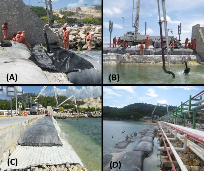
Throughout the installation the labor personnel perceived the advantage of flexibility and speed when handling the textile tube fabric to place it in position and then relatively just wait the filling time. This made possible to simultaneously place several units in place when working above the sea level and to reduce the labor risk required when working underwater. The pipelines were at all times operating while the slopes of the dock infrastructure were rebuilt and the new slope created. Even when the modernization of the pipe stands and pipelines took place next to the dock slope the geotextile tube installation had no interference with these activities, which at the moment represented important cost and time savings of rented machinery for this piping works.
4. OIL TERMINAL TAKEAWAYS
The rehabilitation and modernization of PEMEX Oil Terminal in Lerma, Campeche, will ensure and increase operations and supplies of oil products in the region, foremost diesel and gasoline. The renovation of its facilities using cutting edge technology provides security and livelihood to continue its activities in the coming decades. The use of geotextile tube technology allowed a fast execution, with heavier elements and with less environmental impact compared to traditional techniques, resulting in the durability and stability of the work of protection against sea erosion.
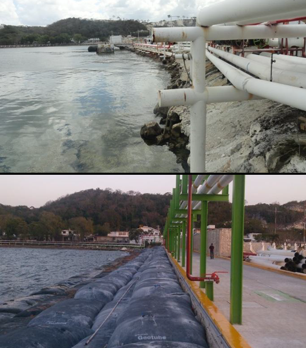
In the case of Castillo Breton Dock, the project will increase the life span of the port infrastructure, increase the number of boat arrivals and enable the port to receive double hull barges; restoring the operational reliability of its facilities, in an scenery of progress with quality and caring for the environment. It was found that the placement and filling of these geotextile tube units with concrete is a simple technique, quick to run with no safety issues, and more important with no logistics and transportation of rocks from quarry involved, which reduce the carbon footprint (environmental impact) during the execution of this kind of projects for port infrastructure.
ACKNOWLEDGEMENTS
The authors gratefully acknowledge management at the PEMEX Oil terminal in Lerma, Campeche and the main contractor GRUPO INDI who were always confident in the right implementation of new construction procedures, particularly Homero Ollervides and Miguel Villalpando for their valuable time and dedication on site during construction. We also appreciate the efforts of Roberto J Bosco for his enthusiasm and strong support in the project documentation, and his attitude for upgrading port infrastructure in Mexico with cutting edge technology.
ABOUT THE AUTHORS
Angel H. Díaz Jr. is Director of Geomembranas y Geosintéticos SA de CV (Mexico). Christopher Timpson worked for TenCate Geosynthetics at the time of the original GeoAmericas 2016 publication but now works with WatershedGeo.
REFERENCES
Alonso, Q. (1972), Design and Construction of Port and Marine Structures, McGraw-Hill, New York, NY, US.
Bezuijen, A. and Vastenberg, E.W. (2012), Geosystems Design Rules and Applications, Taylor and Francis Group, London, UK.
Plaut R. H. and Suherman S., (1998), “Two-dimensional Analysis of Geosynthetic Tubes”, Acta Mechanica, Springer Vienna, 129: 207-218
Koerner, R. M. (2012), Designing With Geosynthetics, 6th Ed., Xlibris Publ. Co., Indianapolis, US.
Mindess, J.F. and Darwin, D. (1996), Concrete 2nd Ed., Prentice Hall, London, UK.


