
Geosynthetics are used frequently to support roads that are built specifically for temporary or limited exposure to very heavy loads. This petrochemical installation project, first presented at GeoAmericas 2016 under the title “Non-Conventional Design Road for Heavy Traffic Load in Soft Soils”, provides a strong example of how geotechnical challenges are answered by matching project-specific design needs with geosynthetic reinforcement materials. The work was authored by Brazil-based Hélio Vronsky Fonseca Adeodato, Rubenei Novais Souza, Silio Carlos Pereira Lima Filho, and Alexandre de Macedo Fernandes Lopes. Geosynthetica published the proceedings for GeoAmericas 2016. GeoAmericas 2020 will be held in Rio de Janeiro 26 – 29 April 2020.
1. PETROCHEMICAL PROJECT INTRODUCTION
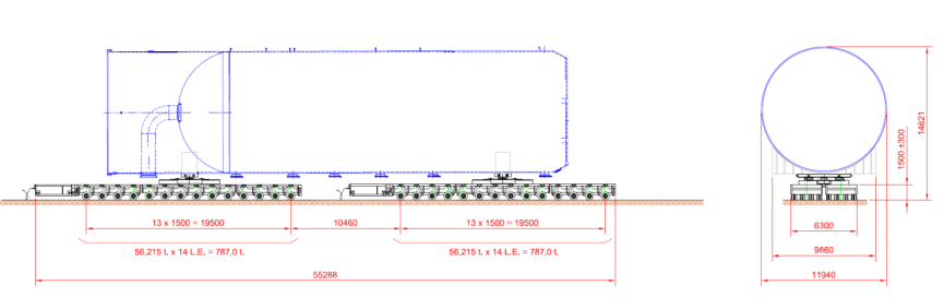
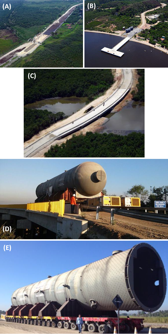
The assembly of the Petrochemical Complex of Rio de Janeiro (COMPERJ) demanded the transportation of very heavy and/or large petrochemical processing equipment (UHOS – Ultra Heavy Over Size), that was not feasible by the existing roads. As result, after the naval transportation to a pier of Guanabara Bay in São Gonçalo – RJ, the equipment was transported to their final destination at the site of COMPERJ, in the municipality of Itaboraí – RJ, by a road of 18 km long specially designed for this purpose, whose subsoil presented a bad ground mostly consisted by a very soft clay layer of low strength and high compressibility. The vehicles used to this on shore transportation were of a special kind with multi-axles applying on the ground an equivalent distributed load between 30 kPa and 70 kPa. Figure 1 schematically shows the configuration of the particular vehicle used for heavier pieces.
2. PREVIOUS AND FINAL DESIGNS
Projects of embankments on soft soils usually have to consider both stability requirements and minimum post-construction settlements. The initial design of the road was developed based on this premise which led to the prediction of solutions involving temporary overloads, soil mixing (dry mix) and stone columns, all the solutions combined with high strength geogrids. At the time, 2010, the excavation and replacement of the soft soil, only when the thickness of the soft clay foundation was less than 3m, by a more competent one were considered unfeasible due to the lack of licensed area for soil disposal in the region.
As the schedule of the project was modified, the works were not initiated until 2012. Then, because of two important changes in the contour conditions of project, the first one associated to the availability of licensed area for a little amount of soft soil disposal in the region and the second associated to the decrease of the available time construction to 10 months, it was necessary a general review of the project in order to adapt it to these new contour conditions.
MORE GEOAMERICAS: An Arctic Project: QC and Leak Location of a Bituminous Liner
During the period of this general review, the team of the project had an insight. As the road was being designed for temporary use, i.e., only for the heavy equipment to be brought to the petrochemical complex area, it would be enough that the embankments fitted only the condition of stability, and the settlement restriction would be of secondary importance in this case. Thus, a solution provided only with geogrids with or without berms would satisfy the stability requirements and allow for the passage of the heavy equipment, ensuring at least the control of excessive differential settlements. Considering then that the new design premises, it was initially studied using equilibrium berms which proved impracticable due to the lack of space. The use of geogrids, on the other hand, was geometrically suitable and also compatible in terms of time construction, since the installation procedure of geogrids follow the earthworks, and the additional time for this would be virtually zero and equal to the execution of the embankment. Because of the long time required for the execution of 250,000 linear meters originally planned of stone columns, the use of this technique in the project was reduced and limited to stretches of bridge abutments where settlements should be more controlled and also to reduce the thrust horizontal in the foundations caused by loading asymmetry.
3. SOFT CLAY AND GEOMETRICAL PARAMETERS
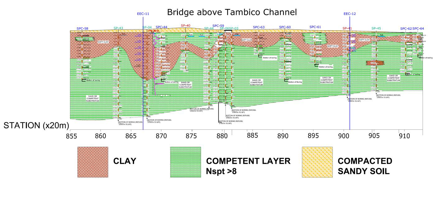
The presence of soft clay was accused in almost over the 18 km of the road. The thickness of the layer of this material ranged from 2m to 16m, as the illustrative profile of a small segment shown in Figure 2.
The soft clay layer along all the road has been extensively studied in terms of the SPT, CPTu and Vane, particularly with a focus on getting the undrained shear strength. The tests performed and the values obtained for the geotechnical parameters are described in Souza et al (2014).
4. ANALITICAL GEOMECHANICAL MODEL
The embankments had a final height about 1.50m, except at the bridge approaches where the embankment was higher, reaching more than 6m in some cases. The typical embankment cross section is shown in Figure 3.
In some segments of the road it was applicable to count with the gain of resistance due the consolidation of the soft clay layer. In these cases, vertical drains were used, in addition to the geogrid, arranged in triangular mesh with 1.0 to 1.50 m side, depending on how much resistance was necessary to gain.
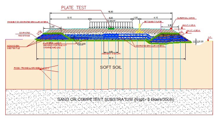
In the rest of the road only geogrids made of high stiffness PVA filaments (Fortrac MP supplied by HUESKER) were used, with values ranging from 6,000 to 24,000 kN/m, depending on the geotechnical characteristics and thicknesses of the soft clay (since the height of the embankment was almost constant), arranged in one or two layers, in an envelope form (wrapped-around in the shoulders). In total, more than 470,000 m2 of geogrids were used.
5. STABILITY AND STRESS-STRAIN ANALYSIS
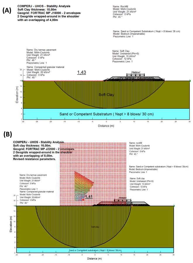
Initially the overall stability of the embankment was analyzed as a rigid body, forcing up the potential rupture surfaces to “enter” and “leave” the ground without intercepting the embankment body, like a large shallow foundation. In this case, the safety factor is independent from the type and quantity of geogrids, being determined primarily by the width of the base of the fill structure.
Subsequently the local stability of the embankment was analyzed forcing the potential rupture surfaces to cross the reinforced zone in order to ensure its stability with a minimum safety factor of the order of 1.40, seeking for the optimization of the amounts and strength of the geogrid layers.
Figure 4 shows some examples of local and global stability analysis of a typical section using the methods of Bishop and Morgenstern-Price through the SLOPE/W program.
In addition to the limit equilibrium analyses, it was also carried out a stress-strain analysis using finite elements method in order to assess the displacement and acting forces in the geogrids. Such analyses were performed using the elasto-plastic model to represent the soil stress-strain behavior and the Mohr-Coulomb criterion for representing the resistance envelope.
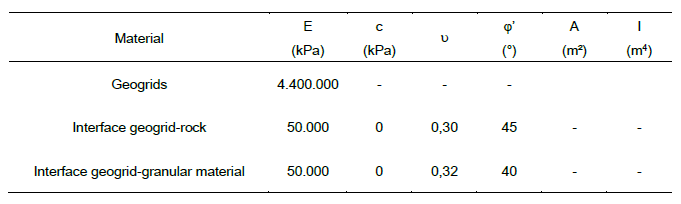
In the elements construction an unstructured type of triangular mesh was used (with 3 nodes) as well as four-sided polygons (with 4 nodes), which sides varied from 5cm to 100cm. The geogrids were represented in the model by beam elements, and its ground contact interfaces have been incorporated to the parameters presented in Table 1.
The analysis were divided into two stages: the first, called the initial phase or phase “in situ”, in which it was calculated the initial tension in the soil; and the second, loading phase, in which it was added to the model the embankment (comprising the rock fill, compacted granular material, dry tarmac and geogrids) and operational overload (live load of 70kPa), equivalent to an over height of approximately 4m of compacted fill.
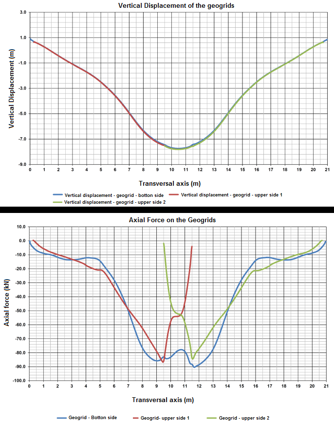
After the analyses it was observed that the vertical displacements of all geogrids layers were virtually identical, with the maximum observed value of 7.8cm. This is the value of the full pseudo-elastic settlement on the vertical axis of the embankment, being 2.1cm due to the construction of the embankment and the other 5.7cm occurring in the passage of the equipment. Figure 5 presents the vertical displacements and axial forces in the geogrid layers obtained with the load from the embankment and the operational load of 70 kPa. These values were considered acceptable for the track operation.
6. JOB CONSTRUCTION
The reviewed design indicated 3 types of solution remained, according to the thickness of the soft soil layer and the proximity of the bridge abutments:
- a) Out of the bridge abutments, soft soil layers less than 3.0m thick: complete removal of the clay layer and replace with compacted fill (sandy material);
- b) Out of the bridge abutments, soft soil layers more than 3.0m thick: compacted embankment reinforced by geogrids, without removal of soft soil (Figure 6a).
- c) Bridge abutments: soft soil treatment with execution of stone columns with a diameter of 0.90m arranged in triangular mesh with 2.0 to 2.50 m side and compacted embankment reinforced by geogrids (Figure 6b).
The quality control of the job (QCP) was also performed by geotechnical instrumentation monitoring, foreseen for the entire via UHOS with particular attention to the bridge abutments sections. In total it was planned to install the following instrumentation: 121 settlement plates, 38 inclinometers (totalizing 531m drilled bores), 10 holes for piezometers (3 piezometers per hole, totalizing 30 piezometers).
The result of this instrumentation, still in systematization phase, will be the subject of a future work. However, one can anticipate that the results of the readings showed up on the forecast, thus consolidating the project principles and carrying out the work as a whole.
7. STABILITY ANALYSIS OF THE EMBANKMENT AT BRIDGE ABUTMENTS
Along the bridge abutment sections, it was required the execution of stone columns in order to reduce the settlements near the bridges and also the negative friction and the horizontal thrust on the piles caused by load asymmetry.
The design analyses of the treatment system with stone columns were made by the method of Priebe (1995). The verification of the efforts deployed in the geogrids was performed using the method of Kempfert et al (2004). The results showed that the spacing of the columns combined with reinforcements adopted in the analysis (limit equilibrium analysis) lead to acceptable tension stresses in the geogrid layers in the heads of the columns as well as satisfactory safety factor against global failure, which shows that the local and global stability of the section was ensured.
These stability analyses were done for both transverse and longitudinal direction. It is interesting to point out that on longitudinal direction were necessary additional considerations. The first one was associated to the representativeness of the two-dimensional analysis. Because of the high load and small width of the multi-axles vehicle it would be very conservative to consider this surcharge directly as a distributed loading on the semi-space. Thus, the two-dimensional analysis on the longitudinal direction was performed considering the load of the multi-axels vehicle divided by the area of the embankment base. The second additional consideration was associated to the position of the multi-axles vehicle near to bridge abutment. During the load passage, that is, while the multi-axles approaches, enters and crosses the bridge, there are various load situations. In an extreme situation, when the machine starts crossing, loading is distributed along its length of 50.0 m, in such a way that surcharge acts by stressing the geogrid on the passive zone, back to the rupture surface. In another extreme situation, the surcharge is located inside the rupture surface (active zone) without pulling out the anchored part of the geogrid. It is assumed that 50.0m long geogrid panels would be enough to cover all situations. As a confirmation, it was found that only the weight of the embankment acting on the geogrid would provide all its structural strength with about 18.00 m of anchored length, even considering only a single face of friction.
Based on the Brazilian Standards, bridges were designed to meet a TR (time of recurrence of floods) of 100 years, which demanded bridge approaches made out of very high embankments, up to 7m (bridge over the river Guaxindiba, for example ). Because of this, the additional implementation of equilibrium berms with stone columns and geogrid underneath the bridge deck were required.
In most cases it was necessary that the geogrid and / or stone columns overlapped the foundation block by the following equilibrium edge, once the longitudinal stability calculations showed that the potential critical rupture circle with the poorest safety factor would pass between the treated soft soil and the foundation block.
The proposed solution, with longitudinal berms under the bridge deck, aimed to improve security in the longitudinal stability as well as presented the advantages of reducing the forces from the loading asymmetry (Tschebotarioff effect) and ensure the stability of the external piles, those of the abutment blocks, during and after their piling works, while it was not concreted the foundation block, since the berm provided a restraint effect on the head of the piles, minimizing their free movement in the soft soil.
Figure 7 shows an example of longitudinal stability analysis performed for this arrangement that was frequently used for the bridge abutment sections in this project.
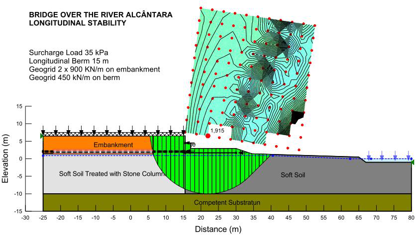
In this example, the embankment was designed to reach the quota +6.50 m reinforced by two geogrid layers of J26000 (26,000 kN/m of nominal stiffness module) to ensure longitudinal stability. In the executive project stage, it was conducted several stability analyzes which resulted in optimized solutions with berms under the bridge deck reinforced by one geogrid layer placed on its base.
8. FINAL REMARKS
This paper briefly describes the development of the succeed design, construction and operation of special road for traffic of multi-axles vehicles loaded with very large and heavy equipment in Rio de Janeiro, Brazil, which treated with very hard constraints as follow:
- Geometric Constraints: embankment very low and with very narrow width, with restrictions on the use of equilibrium berms, exposing almost all its platform to the operation;
- Geotechnical Constraints: very soft soils, with thicknesses of up to 16 m with typical undrained resistance less than 12 kPa;
- Geological Constraints: lowland region in tidal lagoon deposit area, with extensive occurrence of water-bodies, requiring the prediction of several crossings on bridges (17 in total);
- Operational Constraints: compositions of great dimensions and weight (UHOS), up to about 1400 tons of full load and 70 kN/m2 equivalent distributed load, whose transportation should be done at low speed (<5 km/h);
- Planning Constraints: narrow time for execution (10 months);
- The combination of all these factors led to the need to revise the initial basic design, based on the reduction of earthwork volumes and of treatment of soft soils. Finally, the adopted solution was essentially the soil reinforcement with geogrids. The specified geogrids were defined from stability analyses, and the performance of the designed sections was analyzed in terms of limit equilibrium stability and finite element simulations in order to confirm compliance with design requirements in each section.
- Constructive difficulties by the required high levels of strength and the limited space available for anchoring the geogrid were supplanted by detailed definition of the executive project. Geogrids, where necessary, were wrapped-around (overlapping lengths compatible with the forecast tensile loads) and considered as multiple layers.
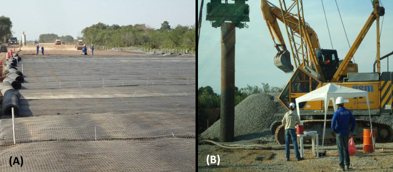
Figure 8 presents, as an illustration of the project described herein, some pictures of diverse construction stages. The road has already been put under operation.
ABOUT THE AUTHORS
Hélio Vronsky Fonseca Adeodato is with Planave S.A. Rubenei Novais Souza is with Petrobras S.A. Silio Carlos Pereira Lima Filho is with Geoinfra Ltda. Alexandre de Macedo Fernandes Lopes works for CSE Ltda.
ACKNOWLEDGEMENTS
The authors thank Petrobras and Planave for the assignment of the data used at this work, as well as the engineers Narciso A. F. Lopes, Jean-Pierre Paul Remy, Giana Laport, Paulo Vitor Cunha, Otavio Eleuterio and André Estêvão Silva for the prestigious collaboration to its edition.
REFERENCES
Souza, R. N.; Souza, G. L. A.; Pinto, T. C.; Soares, A. S.; Viana, E. A. (2014). Propriedades geotécnicas das argilas moles da estrada do COMPERJ (Geotechnical properties of the soft clay of the COMPERJ road), XVII Brazilian Conference of Soil Mechanics and Geotechnical Engineering, Goiania, GO, Brazil.
Priebe, H. J. (1995). The design of vibro replacement, in Ground Engineering, Technical Paper GT 037-13e, Bochum, Germany: 31-47.
Kempfert, H. –G.; Gobel, C.; Alexiew, D.; Heitz, C. (2004). German recommendations for reinforced embankments on pile-similar elements. Eurogeo 3. In: 3rd European Geosynthetics Conference, Geothechnical Engineering with Geosynthetics, München, Germany: 279-284.


