
The International Geosynthetics Society runs a series of high-level workshops that are organized by the IGS Technical Committees. Two of the major TCs are TC – Soil Reinforcement and TC – Stabilization. Both completed highly successful workshops in the past few months. Here, we look at work from Jacek Kawalec and Eugeniusz Koda from GeoAmericas 2016—part of Geosynthetica’s GeoAmericas series. (GeoAmericas 2020 will take place in April 2020 in Brazil.) Kawalec was an organizer of the Stabilization Workshop in Prague in November 2019. He’s also the chair of the upcoming EuroGeo 7 (September 2020, Warsaw). In Kawalec and Koda’s writing, insight into soil reinforcement and stabilization with geogrid technologies can be found, both through exploration of contemporary works and historical accounts. This article was originally published as a paper under the title “Polish Experiences in Using Geogrids in Earth Structures Engineered with Anthropogenic Materials” in the GeoAmericas 2016 proceedings, published by Geosynthetica.
1. INTRODUCTION TO POLISH EXPERIENCES WITH GEOGRIDS
The geogrids are widely used as reinforcements in slopes, walls, roads, and foundations where they are subjected to constant stress throughout their service life (Koerner, 2005). The geogrids are designed to be used in geotechnical structures where soil particles need support from a long term perspective. Due to the high strength and durability, geogrids are commonly used for the construction of the steep slopes and road pavement construction. Especially where the geogrids of rigid node comes to engagement and wedge up soil in the mesh of geogrids. The grain aggregates or soils pass through the mesh of geogrids, partly succumbing wedged in the spaces between the ribs. The strength and stiffness of the ribs prevents displacement of soils on the sides but may then assert to mechanical damage of the material (Webster, 1993; Kawalec, 2010). However, these materials are exposed not only to mechanical impact, but also the influence of the environment in which they are used and subjected to aging process, particularly on polluted areas. The current standards do refer up to 100 years of design life for structures, so geogrid as a part of the component must fulfil also those criteria. The properties of a geosynthetic including geogrids generally depend on time (ISO/TS 13434:2008; EBGEO 2011).
The service life of a structure with a geosynthetic depends mainly on the durability of the geosynthetic. The aging process of geosynthetic materials can be envisioned as a simultaneous combination of physical aging and chemical aging (Rowe and Sangam, 2002; Carneiro et al., 2010). As a result of aging or degradation, several detrimental effects occur in the polymer: loss of additives and plasticisers, change in molecular weight, formation of free radicals and brittleness (Rowe et al., 2008). Geosynthetic materials made from high density polyethylene have a potential for stress cracking, which is a material failure caused by tensile stresses less than the short term mechanical strength. This is characteristic for a brittle fracture without increasing adjacent to the failure. The cracking is usually formed in stress concentration areas or regions in the local microstructure in homogeneities. This phenomenon has two phases: crack initiation and crack growth. Environmental Stress Cracking (ESC) is the bursting of the polymer under tension, when exposed to the chemical environment (Elias et al. 2009). This failure mode can reduce the life of the PE used for critical applications such as reinforcement applications in a landfill.
The first reinforced soil structures was built in France, 1970 and 1971 (Leflaive, 1988). In subsequent years it begun to be used throughout the world, and so for example in the United States, structures of this type were built since 1974 (Bell and Steward 1977).However, in Poland, when it comes to an engineering practice, they have been used for about 30 years (Koda et. al., 1993). The first permanent geogrid constructed in the U.S. was built in 1982 to support a roadway access to Devils Punch Bowl State Park on the central Oregon coast, USA (Bell et al. 1985). Observations in 1993 by Bell indicated that little wall movement had occurred since construction and that the geogrid reinforcement still appeared like new, with no apparent degradation (Allen and Bathurst 2001).
The geosynthetics products in Poland have become more popular since early 90’s. First applications considered mainly filtration (geotextiles), insulating (geomembranes and GCL) and reinforcing (geogrids) products. The reinforcing structures were used for the natural soil and anthropogenic materials (waste) stabilization. During political and economic changes in Poland, a number of industrial factories was restructured or closed. The former industrial sites required complex reclamation works, to adopt them to new development plans. Moreover, there were thousands of old landfills (municipal and industrial) which required immediate reclamation works or final closure of the site. The accelerated transport infrastructure development often passed through brown fields and former industrial sites, particularly on Silesia Region in the southern part of Poland (Kawalec, 2010).
For the purpose of the road construction reinforcement on landfills the geogrids appears to be a significant constructing element. Numbers of landfills are embankment types exceeding 50 m height. The exploitation of such sites usually did not meet earth works framework, what resulted in severe landslides or cavities. The opportunity for the use of geogrids on landfills is a slope engineering practice that assures geotechnical safety design. The basic properties of a mining waste from the area of Silesia region are shown in Table 1. The paper presents examples of applying geogrids as a material reinforcing road structures constructed on ananthropogenic subsoil. The examples also consider improvement of municipal landfills slope stability, as a part of reclamation works for a new development plan (recreational purposes: ski slope, cycle paths, view terraces). The designing details of reinforced structures are described, as well as slope stability analyses and geogrids strength testing which includes analyses of hazardous environment influencing the long term material parameters. In 90’s HDPE geogrids were used for the slope stability reinforcement on two largest sanitary landfills, i.e. Radiowo and Łubna, located close to Warsaw, the capital city of Poland (Koda, 1998).
2. EXAMPLES OF ROAD AND MOTORWAY STRUCTURES ON INDUSTRIAL SITES
A huge investment into the infrastructure in last 15 years, as an effect of Poland joining European Union, resulted in numbers of road and motorway projects executed in South Poland and Upper Silesia region. A typical example is a motorway A4 passing by Silesia on the route from Germany to Ukraine. On 9,5 km long section between junctions “Sośnica” and “Wirek” several geosynthetic applications were used including:
- Slope reinforcement of high embankments formed from man-made soils to increase their Factor of Safety,
- Protection of motorway pavement against direct influence from deep coal mining activity,
- Protection of motorway embankment base against influence from deep coal mining activity,
- Grade separation structures along roads crossing the motorway.
Upper Silesia is a highly industrial region with many coal mines as well as power plants and steel mills. As a result hundreds of million tons of an anthropogenic material is located on heaps. The anthropogenic materials are becoming commonly used for a road construction purpose in this region. The whole section of motorway A-4 was constructed with the use of the anthropogenic materials as well (Figure 1). Three types are used most often: burnt and unburnt coal mining shales and blast furnace slags. Because of the nature of anthropogenic materials it becomes important to properly select polymer of which geosynthetic materials are made of, to avoid risk of degradation over time. In the case of A-4 project the geogrids made from Polypropylene (PP) and High Density Polyethylene (HDPE) was chosen.
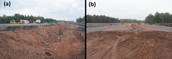
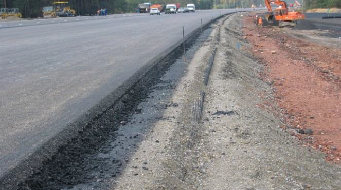
Polish road construction regulations for embankments of height over 6,0 m requires stability checks using FOS >1,5 criterion. Such high requirements often result in need for slope reinforcement. In this case all slopes higher than 5m were reinforced by layering of uniaxial HDPE geogrid placed on every second layer of the compacted fill material (each compacted layer made of burnt coal mining shales had 0,5 m thickness) (Figure 2). The pavement of the motorway A-4 had 27cm thickness of asphalt layers placed on 72 cm (22+20+30) thick aggregate base and sub-base layers. The upper 22 cm base layer was stabilized with a polypropylene geogrid (Figure 3). The pavement design was made based on mechanical – empirical methodology incorporating an effect from stabilizing the geogrid in aggregate layer on a pavement fatigue life extension. Thanks to the confinement effect, understood as a mechanism of interlock between the geogrid and aggregate particles, a stabilization of aggregate layer is taking place. The stabilization is understood as a beneficial consequence on serviceability of unbound aggregate layer via inhibition of the movement of the particles of such layer under applied load. In case of potential mining influences resulting in surface deformation, the stabilization of a base layer gives additional support to the pavement structure.
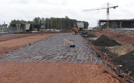
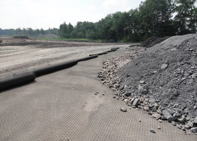
In this application base layer of the embankment is placed over geomattress made of an unbound aggregate stabilized with two layers of a geogrid. Again, due to the fact that the aggregate selected in the project for this part of works was blast furnace slag polymer, thus it had to be polypropylene. Such geomattress creates a quasi-stiff platform at the base reducing most of deep mining deformations on a surface and allow rapid construction (Figure 4). Such geomattresses were successfully used also on other road and motorway sections in Upper Silesia as a protective layer against mining influences. Some of them were monitored and the final observation from monitoring confirmed their positive impact on reduction of mining influenced deformations of above mattress resulting in the pavement evenness over longer time (Figure 5).
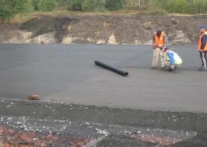
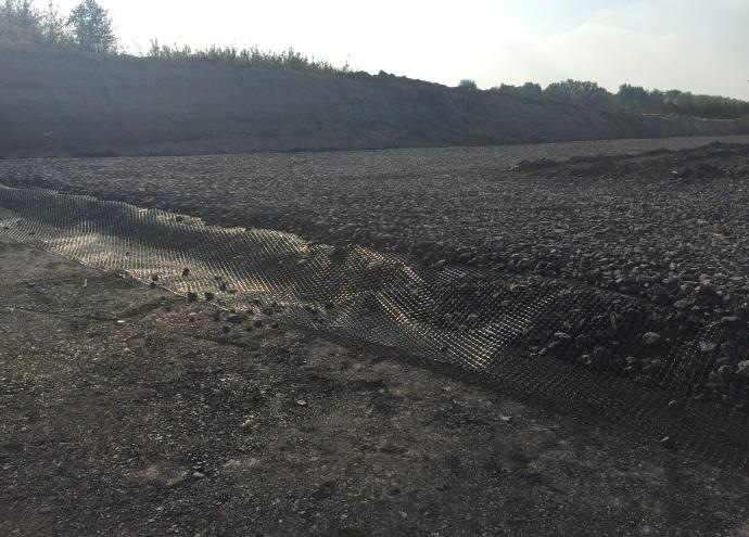
The motorway A-4 was completed in year 2005. Since that time many other projects have been using combination of geogrids and man-made soils. Several expressways and main roads were constructed with mining waste in use (Figure 6). In many locations in Upper Silesia, the coal mining waste is disposed on landfills. Sometimes such landfills are higher than 50 m and of area of tens of hectares. If the landfill is located close to any infrastructure or residential areas buttresses are required. Typically such buttresses are made with exactly the same deposited waste material stabilized and/or reinforced with geogrids. An example of base layer of a landfill buttress is shown on Figure 7.
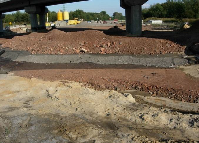
Another interesting application of embankments constructed with anthropogenic materials is reduction of earth pressure on the back wall of bridge abutment in mining activity areas (Figure 8). According to Polish Design Code earth pressure used for calculation should be doubled, what results in need for quasi reinforced structures made just behind abutments. Most of bridges along the motorway A-4 were constructed with such structures behind walls reducing pressure from 45 to 100%.
3. EXAMPLE OF SANITARY LANDFILL SLOPES REINFORCED WITH GEOGRIDS
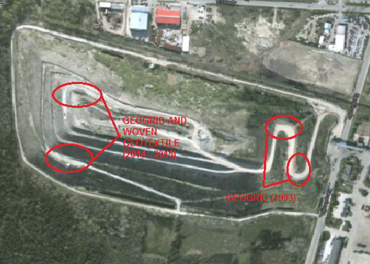
Radiowo landfill, covering an area of about 16 hectares and more than 60 meters above ground, is located at the north-western border of Warsaw, the capital city of Poland (Figure 9). In the years 1961 – 1991 the municipal waste was disposed there, and since 1992 it has been a technological facility receiving ballast waste from the composting plant. At high steep slopes key issue was to ensure their stability, and therefore there was a comprehensive study of mechanical properties of waste carried out. Different reinforcement techniques were used, depending on the slope inclination, the type of waste, provision of land next to the landfill and the state of landfill body development (Koda and Osiński, 2015).
In 1993, reclamation works began on the landfill. They mainly included safety solutions in terms of geotechnical formation of the landfill body. In order to improve the conditions of the northern slope stability and to make the structure underpinning the main landfill access road l, the retaining wall structure was used (in the area of the square filling waste), as well as slope engineering and HDPE uniaxial geogrid horizontal reinforcements (Figure 9).
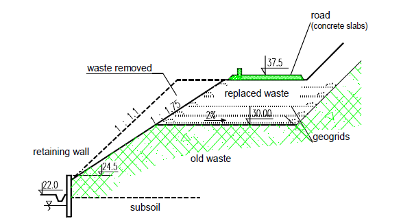
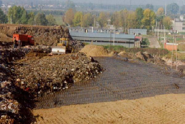
In order to improve the stability of the slope (30 m high) located close to Kampinoska Street (Figure 10), there have been done: the steel retaining wall, moderate slope inclination from 1:1 to 1:1.75, replacement of non-composted waste in the road foundation (5 m deep) and the horizontal reinforcement with uniaxial HDPE geogrid (Figure 11). The geogrid that was installed on a landfill is exposed to mechanical and chemical factors (e.g. mechanical stresses by load and trucks, changes in a wide range of pH values and high temperatures) as well as it is subjected to the changing weather conditions. The geogrid product samples, which were installed more than 20 years ago in the old sanitary landfill were exhumed. The physicochemical changes observed by Differential Scanning Calorimetry (DSC) and FT-IR spectroscopy are discussed in relationship to the observed changes in HDPE mechanical properties from the strength tests. Several physicochemical properties of the HDPE geogrid samples virgin and after 20 years of landfill aging were compared. Mechanical properties changed slightly (Kiersnowska et al., 2014).
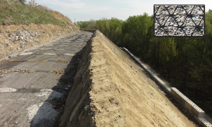
Nowadays, this landfill site is planning to be adopted as a winter sports activity complex. The construction plan has already been accomplished and accepted by a legal body, which is a requirement when considering new development plan for contaminated sites. In southern part of Radiowo landfill a retaining wall was constructed, where concrete elements and soil reinforced with woven geotextile are independent and separated by sandy backfill drainage (Fig. 12). In the upper part of the slope HDPE geogrid reinforcing a landfill slope was proposed. The stability analyses were computed with the use of limit equilibrium method (Bishop) and FEM. The results of analyses obtained from laboratory tests of tensile strength of woven geotextile and geogrid samples were used for the soil reinforcement as a part remedial working plan on the landfill. Geosynthetics in the landfill can be exposed to elevated temperatures so the aim of the research was to determine tensile strength and deformation at different temperatures from 0°C to 80°C. The results of these tests were also taken into account in the slope stability analysis and selection of geosynthetic products to install.
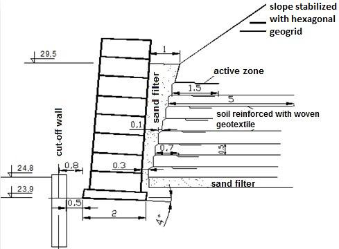
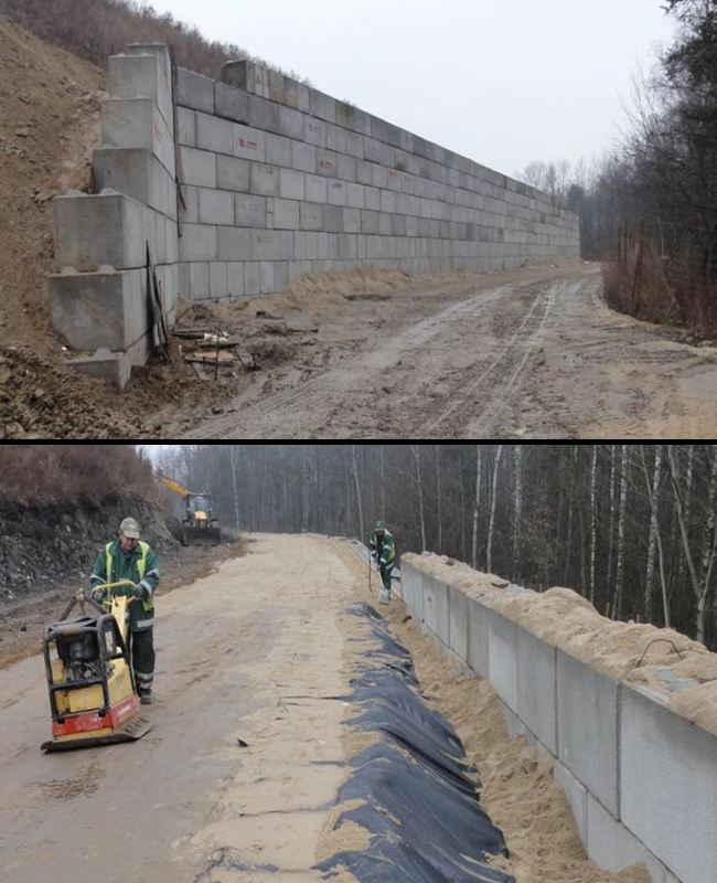
The retaining structure in the southern east part of the landfill was designed as a concrete wall of 120 m length and 5.8 m height. The wall was constructed on 2 m wide foundation pad. The inclination of the pad is 4° towards the slope. The foundation was also equipped with prefabricated concrete elements of dimensions 0.8×0.8×1.6 m. The cross section of the retaining wall is presented on Figure 12. The geotextile reinforced soil was isolated from a concrete face by sandy drainage. In total there were 8 reinforce soil layers constructed (Figure 13). Due to the specific location and to avoid excessive side deformations, there were additional slope reinforcing elements applied (Figure 14). Those were 5 layers of hexagonal HDPE geogrids above the concrete retaining wall.
4. CONCLUSIONS FROM POLISH EXPERIENCES WITH GEOGRIDS IN SOIL STRUCTURES
The paper presents examples of geogrids application on engineering structures designed on brownfield and landfill sites. The first attempts of such structure design in Poland were (rarely) overtaken in early 90’s. Then after, when Poland joint European Union, the infrastructure development rapidly increased thus using geogrids has become more common also for landfill reclamation purposes. The initial applications in 90’s allowed testing the durability of such materials being used in hazardous anthropologic environment (industrial and municipal leachate), and then verification of earth works design for the future investments. The research confirmed high resistivity of HDPE geogrids to sever landfill conditions and industrial contaminations. The recent investments in Poland clearly show significant increase in geosynthetic materials demand, especially for the purpose of engineering structures reinforcement and natural slope stability improvements.
ABOUT THE AUTHORS
Jacek Kawalec is the Director of Technology Eastern Hemisphere for Tensar International and the Chairman of Eurogeo 7 (6 – 9 September 2020, Poland). Eugeniusz Koda is the Dean in Faculty of Civil and Environmental Engineering at Warsaw University of Life Sciences – SGGW, Warsaw, Poland.
REFERENCES
Allen T.M. and Bathurst R.J. (2002). Observed long-term performance of geosynthetic walls and implications for design. Geosynthetics International, 9, No. 5-6.
Bell J.R. and Steward J.E. (1977). Construction and observations of fabric soil walls. International Conference on use of fabrics in Geotechniques. Paris, Vol. 1: 123–128.
Bell J.R., Szymoniak T. and Thommen G.R. (1985). Construction of a steep sided geogrid retaining wall for an Oregon Coastal Highway. Polymer Grid Reinforcement Conference, London, UK, Thomas Telford ed., 198-202.
Carneiro J.R., Almeida P.J. and Lopes M.L. (2010). Resistance of high-density polyethylene geonets against chemical ageing. 6th International Congress on Environmental Geotechnics. New Delhi, India, 909-914.
EBGEO (2011). Recommendations for Design and Analysis of Earth Structures using Geosynthetic Reinforcements. Ernst & Sohn Verlag, Berlin, Germany.
Elias V. (2001). Long-term durability of geosynthetics based on exhumed samples from construction projects. Report No. FHWA- RD-00-157, U.S. Department of Transportation, Federal Highway Administration. USA.
Gryczmański M., Kawalec B. and Kawalec J. (1997). Coal mining waste as a structural material in polish civil and water engineering, 13th International Conference on Solid Waste Technology and Management, Philadelphia, USA, 23-30.
Kawalec J. (2010). Stabilisation of the subsoil with geogrids. Inżynieria Morska i Geotechnika, 4: 522-530 (in Polish).
Kiersnowska A., Koda E., Fabianowski W. and Kawalec J. (2014). The impact of chemical and environmental factors on the mechanical parameters of HDPE geogrid, e-Book 7th International Congress on Environmental Geotechnics, Melbourne. 696-705.
Koda E., Szymański A. and Wolski W. (1993). Field and laboratory experience with the use of strip drains in organic soils. Canadian Geotechnical Journal, 30: 308-318.
Koda E. (1998). Stability conditions improvement of the old sanitary landfills. 3th International Congress on Environmental Geotechnics, Lisboa, Portugal, Vol. I: 223-228.
Koda E. and Osiński P. (2015). Application of alternative methods of slope stability improvements on landfills. 16th European Conference on Soil Mechanics and Geotechnical Engineering. 5: 2717-2722.
Koerner R.M. (2005). Designing with Geosynthetics. 5th Edition, Prentice Hall, Englewood Cliffs, New Jersey, USA.
Leflaive E. (1988). Durability of geotextiles: the French experience, Geotextile and Geomembranes, 7: 23–31.
Rakowski Z. and Kawalec J. (2009). Mechanically stabilized layers in road construction. 27th International Baltic Road Conference , Riga, Latvia, section A2 Road Construction.
Rowe K., Islam M. Z. and Hsuan Y.G. (2008). Leachate chemical composition effects on OIT depletion in an HDPE geomembrane. Geosynthetic International ,15: 2.
Rowe R.K. and Sangam H. (2002). Durability of HDPE geomembranes. Geotextiles and Geomembranes, 20: 77-95.
Technical Report European Organization for Technical Approvals (EOTA) (2012). Non-reinforcing hexagonal geogrid for the stabilization of unbound granular layers by way of interlock with the aggregate”, TR41.
Tensar (1990). The long-term performance of Tensar geogrids. Tensar/Nelton LTD, United Kingdom.
Webster S. L. (1993). Geogrid reinforcement base courses for flexible pavements for light aircraft. Technical Report GL-93-6, US Army Engineers Water-ways Experiment Station, Vickburg, MS.


