
Following news that Ian Peggs, founder of Geosynthetica, is retiring from I-CORP International (though not retiring completely from geosynthetics), we thought we’d look back on some of his most provoking writings on this site. Whales and stress cracking are certainly the topics that have generated the most eye-catching works. We will re-release more of this work soon (including with some updates).
Here, we look back at a 2018 update of his original 2011 primer on whales (or, bubbles) in geomembrane lining systems at wastewater treatment plants and similar facilities. The end section invites contributions of other notes from the field. We (and Dr. Peggs) welcome your input!
WHALES IN WWTP & OTHER GEOMEMBRANE LINING SYSTEMS
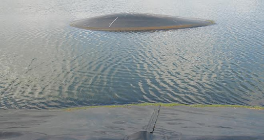
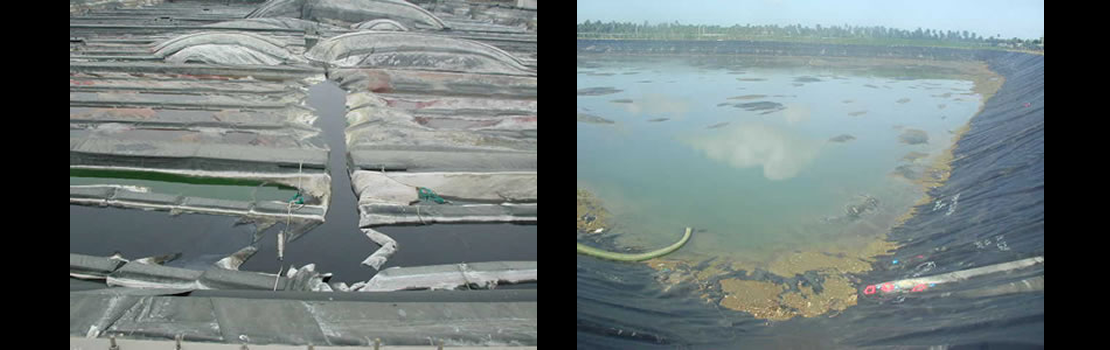
By Ian D. Peggs – There continue to be failures of HDPE geomembrane lining systems in waste water treatment plant (WWTP) lagoons and farm manure ponds. These geomembrane whales, which are bubbles that develop under the geomembrane, are generally caused by leakage through the liner, the inability to remove leakage, the generation of methane, and the subsequent inability to vent the methane.
The following considerations on geomembrane whales were first published on Geosynthetica in May 2011. Here, we update our thoughts, taking into account larger filed discussions that have occurred in the years since. We also invite your insight in the comments section beneath this post or in the comments section of the corresponding social media posting of this article on LinkedIn, Facebook, and Twitter.
PREVENTING HDPE GEOMEMBRANE WHALES
When using high-density polyethylene (HDPE) geomembrane liners, carefully consider the following points during the design and installation of these lining systems:
- Assume that the geomembrane liner will leak a little. It may not, but it probably will.
- Identify an acceptable leakage flow rate. This is the Action Leakage Rate (ALR) above which the responsible holes must be found and repaired.
- There is now a suggestion for Action Leakage Rates (ALRs) as a function of depth in deep ponds. See EuroGeo 6 proceedings for a number of papers discussing lining systems and leakage rates.
- If there is a leak and it is not prepared for, leak damage can be extensive and expensive.
- Whatever ALR is assumed, there should be a leak drainage, collection, and removal system under the geomembrane to handle this leak flow rate.
- Leaked liquid must be continuously removed to minimize the generation of methane.
- The floor of the lagoon should be sloped to a sump. It should not be flat.
- A sloped geocomposite leak detection system (LDS) under the liner is desirable for rapid reporting of a leak anywhere in the liner and for allowing gas venting upslope to air vents.
- A network of geocomposite strips, one-way valves, or candy cane vents most often do not work since the peaks of the whales do not happen in the same place the next time.
- A light geotextile will not function as leak drainage and gas venting system.
- If concrete embedment strips are used for sealing liner to concrete structures ensure the strip is well-embedded in concrete — no voids underneath, and no gaps in concrete between strip butt joints or beveled corners.
- Embedment strips and batten strips should be in same plane as liner, not perpendicular with only a short distance between corner and seal.
- Ensure grinding in preparation for welding is continuous along strip surface.
- When welding, allow for larger heat sink in strip than in geomembrane.
- Batten strip seals must have gasket between geomembrane and concrete.
- Batten strip bolts should not be cranked tight — the objective is to compress the gasket no more than its compressive yield strain.
- Adjacent soil compaction is more effective if there is a slight slope on vertical concrete walls.
- Use geotextile cushion between geomembrane and concrete.
- Try to avoid underwater seals. For instance, seal reservoir concrete roof columns at top rather than bottom.
- Liner should be fully supported when facility is filled. This may need some slack in liner between fixed points if installation is done at higher temperatures. If installation is done at lower temperatures no slack need be built in.
- Amount of slackness depends on material coefficient of thermal expansion and temperature difference expected
- The only temperature of interest is the geomembrane temperature.
- Liner under aerators should be ballasted (concrete slab) to prevent uplift and to provide support for aerator at low water levels.
- Perform a liner integrity survey on the complete liner. Design should allow for survey to be done.
- If all parties come to an agreement on the definition of ALR, it will save considerable discussion, time, and cost.
SELECT ADDITIONS FROM DIALOGUE WITH READERS
- Don’t plan on puncturing the whales to get rid of them. – Glenn Darilek, Leak Locations Services, Inc.
- “The most interesting advice I was ever given on whales came from an old timer at a WWTP [more than] 25 years ago. When I asked what he did to get rid of them, he smiled and patted the shotgun hanging in the rack of his pickup truck. – Mark Smith
- Never forget that the primary objectives are to minimize leakage, remove leaked liquids, and vent gases. – Ian D. Peggs
ADDITIONAL RESOURCES ON GEOMEMBRANE WHALES
- Avoiding Whales in Anaerobic Digesters
- GSI White Paper 30: In-Situ Repairs of Geomembrane Bubbles, Whales, and Hippos
- Whales in Geomembranes: Stronger than Concrete
- Drainage and Venting of Geosynthetic Containment Systems
Ian Peggs is the former president of I-CORP INTERNATIONAL, Inc. He can be reached at icorp@geosynthetic.com.


