
 By Daniele Cazzuffi – RemTech 2013 will be held 18-20 September 2013 in Ferrara, Italy. This marks the 7th edition of a growing international event focused on remediation technologies. The two-part article presented here, which is adapted from the paper “Safety containment systems, including geosynthetics as possible prevention in the event of hydrocarbon tanks failure,” is a strong example of the types of topics that RemTech participants exchange knowledge on. Part 1 introduces the subject and the primary research. In Part 2, the results of the research are presented. Seven types of geomembranes were included in this study.
**
The results of the following tests are illustrated: nominal thickness, thermo-gravimetric analysis, tensile stress and strain, tear strength. As far as the chemical-physical properties are concerned, density and cold bending of all tested materials do not effectively change. Moreover, the Shore A hardness related to all types of geomembranes decreases, if compared to the virgin sample value, more quickly during the first two months, more slowly later; in particular, after eight months of exposure to diesel fuel, the VLDPE geomembrane is subjected to the highest decrease (about 16%), while the hardness of the other six types of geomembranes decreases in the range of 10%.
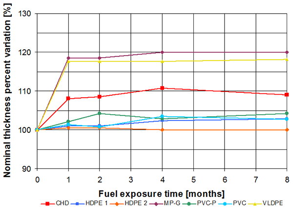
As far as thickness behaviour is concerned, Figure 1 illustrates the percent variation of nominal thickness vs. exposure time to diesel fuel.
As it can be seen, HDPE 2 maintains the same thickness after eight months and PVC, PVC-P and HDPE 1 are subjected to an increase of about 3-4%, while CHD, VLDPE and MP-G seem the most affected by a prolonged contact with diesel fuel, because their thickness increase of about 10%, 18% and 20% respectively: these ranges of increase are already evident after two months of exposure.
The increase in nominal thickness is surely connected to a diesel fuel absorption.
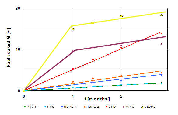
The thermo-gravimetric analysis allowed to calculate the quantity of fuel soaked by geomembranes and the results are represented in Figure 2.
The very low density polyethylene geomembrane (VLDPE) soaks up more diesel fuel than the other types: in fact, the VLDPE geomembrane soaks up about 18%, while the modified polyethylene glass fibres reinforced geomembrane (MP-G) and the modified high density polyethylene geomembrane (CHD) absorb in the range between 10% and 15%. On the contrary, the high density polyethylene geomembranes (HDPE 1 and 2), the polyvinilchloride geomembrane (PVC) and the flexible polyvinilchloride geomembrane (PVC-P) soak up a minimal amount of diesel fuel (about 4.5% for HDPE and about 2% for PVC). In fact, MP-G, VLDPE and CHD geomembranes are subjected to higher increases in thickness, if compared to HDPE and PVC geomembranes: this correspond to a larger quantity of diesel fuel absorbed.
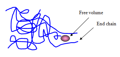
The structure of the polymer matrix could explain the behaviour of the different polymers in presence of solvents.
Due to the fact that polymers are made of long molecules, the geomembrane requires slow cooling rates and/or long time to reach equilibrium volume after manufacturing.
As a result, a relatively small part of the total volume always exists that is not fully occupied by molecules, which is called the “free volume” (Figure 3). Its amount for a given mass of polymer depends on the number of chain ends, hence the number of chain and the degree of polymerisation. Using this interpretation, solvents, like diesel fuel, can permeate the polymers (the absorption phenomenon observed) thanks to the volume of the polymer mass not occupied by molecules.
Thus, the solvent molecules, when penetrate into the material through the free volume, break weak inter-chain interactions, increasing the distance between polymer chains and reducing their cohesion: this typically leads to an increase in dimensions (swell) and to a loss of stiffness, as described by Kay et al., 2004.
As illustrated in Figure 2, where the fuel soaked percentage M is plotted vs. the square root of the time, data related to all geomembranes, except CHD and VLDPE, fit a linear interpolation of the Fick’s law, as suggested by Weitsman (1986):
If we assumed D as a constant, the relationship (1) becomes a line crossing the axes origin, as it appears clear for HDPE, CHD and PVC. On the contrary, the Fick’s law cannot be applied to MP-G and VLDPE geomembranes.
In both cases, it should be said that the diffusivity coefficient isn’t constant. MP-G is a glass fibre reinforced polyethylene geomembrane : the presence of the reinforcement explains why the diffusivity coefficient isn’t constant and consequently justifies the anomalous absorption of diesel fuel of MP-G illustrated in Figure 3. In fact, after the first month of contact, the data related to MP-G can be interpolated by a line with the same slope as both HDPE 1 or HDPE 2, as if the effect of the diesel fuel on the polymeric matrix prevails after the first month, while in the first thirty days the absorption through the reinforcement dominates. An explanation of the VLDPE behaviour in terms of diesel fuel soaked seems more difficult, because this type of geomembrane is not a fibre-reinforced.
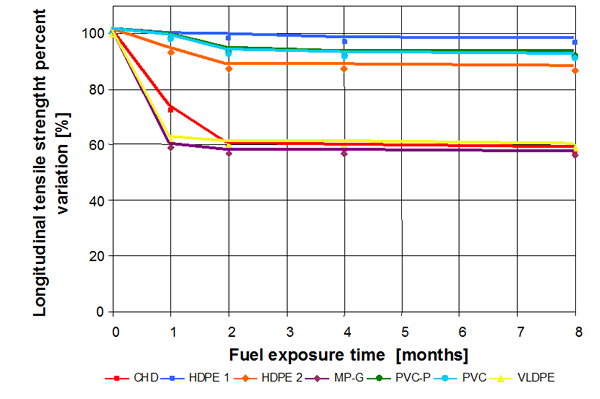
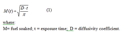
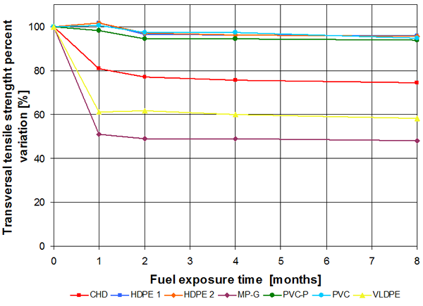
In Figures 4 and 5 the percent variations of tensile strength in longitudinal and transversal directions are illustrated, while in Figures 6 and 7 the percent variations of tensile elongation at break in longitudinal and transversal directions are shown. The geomembranes can be subdivided in two groups in terms of tensile behaviour: HDPE 1, HDPE 2, PVC and PVC-P in the first group, CHD, MP-G and VLDPE in the second one. In fact, the tensile strength in longitudinal direction (Figure 4) decreases less than 15% after 8 months for the first group, while about 40% for the second one.
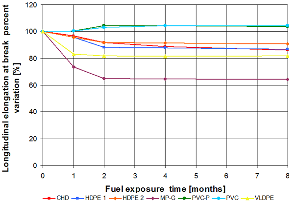
In terms of tensile strength behaviour in transversal direction (Figure 5), the geomembranes belonging to the first group exhibit percent variation less than 10% after eight months, while CHD, VLDPE and MP-G percent variation differ one from each other in a more marked way and ranging from 25% to about 52%. In particular, MP-G retains less than 50% of tensile strength after eight months of contact with diesel fuel. Variations in tensile strength occur within the first two months of contact with diesel fuel, as it is the case also of the tensile elongation at break, both in longitudinal direction (Figure 6) and in transversal direction (Figure 7). As it was expected (Kay et al., 2004), all types of geomembranes exhibit a decrease in the stiffness values, due to the penetration of solvent molecules into the material.
In particular, both types of PVC geomembranes exhibit a reduction in stiffness values due to a reduction in the tensile strength and to a contemporary increment in the strain. On the contrary, the other types of geomembranes show a decrease in the stiffness values, due to the combined effect of a reduction in the tensile strength and of a corresponding smaller reduction in the tensile strain.
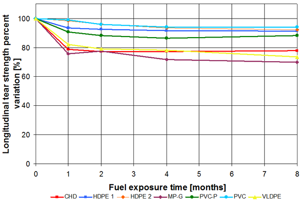
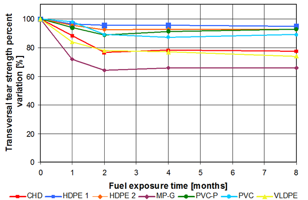
Figures 8 and 9 show tear strength behaviour in longitudinal and transversal directions respectively. Also in the case of tear, as for tensile tests, the geomembranes can be subdivided in two groups: HDPE 1, HDPE 2, PVC and PVC-P in the first group, CHD, MP-G and VLDPE in the second one. Again MP-G is subject to the higher decrease of tear strength (about 30% in both directions).
CONCLUSIONS
In order to determine the evolution vs. time of chemical-physical, mechanical and hydraulic properties of seven different types of geomembranes, different samples of HDPE, PVC, PVC-P, CHD, MP-G and VLDPE were kept in contact with diesel fuel for a maximum term of eight months. Laboratory tests were performed on the virgin material samples and on the samples respectively after one, two, four and eight months of contact with diesel fuel. The obtained results allow to define how diesel fuel affects the geomembrane behaviour; in particular, the following considerations could be settled.
- The increase in nominal thickness, due to a swelling of the geomembranes in consequence of a diesel fuel adsorption, is quite large (about 20%) for MP-G and VLDPE geomembranes and still significant (about 10%) for CHD geomembranes, while it is almost negligible (less than 5%) for high density polyethylene (HDPE) and polyvinilchloride (PVC) geomembranes.
- Correspondingly, the action of the diesel fuel on high density polyethylene (HDPE) and polyvinilchloride (PVC) causes negligible alterations of mechanical properties both in tensile and tear tests, while the tensile and tear characteristics of CHD, VLDPE and MP-G geomembranes are subjected to a more marked reduction.
According to the obtained results it can be said that MP-G, VLDPE and CHD geomembranes are the most affected by a prolonged contact with diesel fuel.
Finally, the greatest variations of all considered properties were registered within the first two months, whereas after this period they remain substantially unchanged.
It must be considered that a secondary containment system provides an essential line of defence in the event of a failure of the primary containment such as oil containers and bulk storage containers: this system provides temporary containment of spilled oil until the appropriate response actions are taken to abate the source of the discharge and remove oil from areas where it has accumulated before the oil reaches the soil, rivers, lakes, wetlands, etc.
In general terms, it could be expected that geomembranes will be directly exposed to oil for a short period of time, i.e. during cleaning-up and reparation operations.
Therefore the good compatibility between geomembranes and diesel fuel should be assured primarily in the short term: from the obtained results, considering the tests performed after one and two months of exposure, PVC and HDPE geomembranes appear to be the most suitable for the considered application.
However, it should be considered also the long term behaviour of geomembranes permanently installed as secondary containment. In fact geomembranes should be chosen based on their capacity to withstand working conditions even in the long term: therefore the selected geomembranes should exhibit not only good compatibility with diesel fuel, but also resistance to UV degradation (in particular for exposed working conditions), excellent behaviour vs. puncture, hold up to thermal expansion and contraction, resistance to environmental stress cracking (for PE materials) and finally withstand long term contact with whatever the tanks hold, from unrefined oil to jet fuel.
REFERENCES
EPA (2005). “Spill Prevention Control and Countermeasures Guidance for Regional Inspectors”. Office of Emergency Management EPA 550-B-05-001, U.S. Environmental Protection Agency, Washington, DC, USA.
Kay, D., Blond, E., Mlynarek, J. (2004). “Geosynthetics durability: a polymer chemistry issue”.Proceedings of the 57th Canadian Geotechnical Conference, Quebec City, Canada.
Shehane, W. (2001). “Updated containment on Craney Island”. Geotechnical Fabrics Report, Volume 19, Number 6, August, pp.36-37.
SLAC (1997). “Secondary Containment Technical Basis Document”. SLAC-I-750-0A16E-001, Stanford Linear Accelerator Centre, Menlo Park, CA, USA.
Weitsman, Y. (1986). “Moisture in composites: sorption and damage”. Technical Report Mechanics and Materials Centre, Texas A&M University, College Station, TX, USA.
www.xr-5.com . “XR-5 lines jet fuel tank farm at Denver Airport”. Case histories, Case study 2.
See PART 1 for an introduction to fuel tank farm secondary containment
Dr. Eng. Daniele Cazzuffi works for CESI SpA and is the chair of RemTech 2013′s scientific committee. He previously served as the President of the International Geosynthetics Society (IGS) Council.


