Here in Part 2 of 2, Gordon Keller looks at multiple case studies of GRS designs. In Part 1, he focused on design and benefits.GRS bridge abutments have been typically produced savings of more than 25% versus traditional designs and are much faster to construct.
CASE HISTORIES
Alaska GRS Bridge Abutment Project
 |
The United States Forestry Service (USFS) has the special challenge of designing permanent bridges and associated bridge substructures for low-volume, single-lane roads in remote areas of the Tongass National Forest, in southeast Alaska. Historically in that region other Mechanically Stabilized Earth (MSE) walls had resulted in considerable cost savings over conventional structures. GRS bridge abutments using geogrid reinforcement were a logical choice in this remote tidal area. In addition, protection from long-term ultraviolet light was necessary when considering geosynthetics as a reinforcing material.
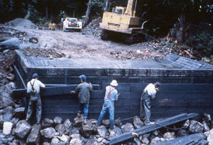
The 3.7 m (12 ft) high GRS abutment wall designed for the Tongass NF project had three vertical faces, including a front face and two wing-walls. High density polyethylene (HDPE) geogrids were used for reinforcement in the bridge abutment walls. Vertical spacing for the geogrid was 30 cm (11.8 in) near the base of the wall and 15 cm (5.9 in) near the top of the wall. A free-draining granular material was used for the wall backfill.
The two external design concerns were UV degradation and protection against floating debris. They were addressed by attaching a 50 mm (2 in) thick treated-timber facing that covered the full height of the wall. On this project two GRS abutment walls were constructed to support the 15.1 m (49.5 ft) long, precast, double-tee concrete bridge.
Feather Falls Trail Bridge Using GRS Abutments
 |
A small trail bridge was replaced in 1999 on the Feather Falls trail, a popular recreation area on the west side of the Plumas National Forest in Northern California. GRS abutments were selected for this project because of the deeply incised and narrow channel, such that the abutment locations were placed well above the channel high water level. Also the area was remote and without road access, such that the bridge materials had to be flown in with a helicopter. Thus use of relatively small, light weight materials, and an easily constructible design were very desirable. On-site rocky soil was used in the reinforced soil backfill.
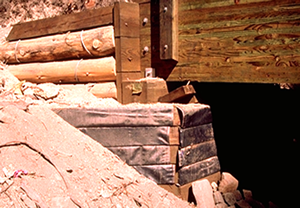
The basic design involved a timber faced, geotextile reinforced abutment, with a geocomposite drain placed behind the GRS abutment walls, and a timber sill placed on the wall to support the two 12 meter (40 foot) long glue-laminated timber bridge girders. The abutment heights were 1.5 and 2.4 meters (5 and 8 feet) high, using 15 cm x 15 cm (6 x 6 inch) treated timbers for facing material. The reinforcement geotextile was placed in 15 cm (6 inch) lifts, with an average length of 2 meters (6 feet). Most geotextile was sandwiched and nailed between the timbers, but the top four lifts were wrapped around the outside of the facing timbers for maximum connection strength.
The entire construction of the bridge required approximately two weeks, using all hand labor (except for flying in the girders and timbers by helicopter) with a crew of 2 people. Construction was straightforward and simple, with the exception that an additional rock drain had to be placed under one of the abutments due to groundwater encountered. Also the toe of both abutment walls were buried 60 cm (2 feet) deep to offer scour protection against a possible debris slide in the drainage.
Mammoth GRS Bridge Abutments
 |
Two bridges near the resort mountain community of Mammoth Lakes, California were reconstructed using Geosynthetic Reinforced Soil (GRS) abutments. The existing concrete structures, both located on the heavily traveled Lake Mary Road within the Inyo National Forest and owned by the U.S. Forest Service, were built in the 1930’s and showed signs of deterioration including longitudinal cracking beneath the bridge decks resulting in the exposure and degradation of reinforcing steel.
Due to a short construction season in this area, the contractor submitted a value engineering proposal to substitute GRS supported spread footing abutments for the as-bid concrete pile foundation. There was a requirement that the free standing existing stone masonry abutments experience minimal lateral earth pressure from the new design. Also the GRS abutments had to meet rigorous design criteria which included a 14.4 kPa (300 psf) design snow load, at an elevation of approximately 2,800 m (9,000 feet) and seismic peak ground accelerations of 0.40g to 0.50g for the bridges in this seismically active area. Scour was not a design consideration at either site since each bridge was located at the outlet works of their respective lakes, and the channels were armored with a concrete pavement.
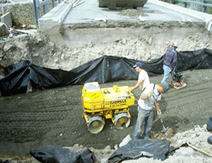
The actual GRS abutment design at each bridge reflected a design philosophy of utilizing closely spaced geosynthetic reinforcing layers placed between well-compacted quality backfill material. In this manner a reinforced composite backfill with improved stiffness and ‘cohesive’ properties was obtained and lateral earth pressures at the face of the wall were minimized between reinforcing layers. Reinforcement layers were spaced at 0.15 m (6 inches) and locally available high quality pit run material utilized as backfill and compacted to 95 percent of the maximum dry density. A 35 kN/m (200 lb/in) polypropylene geotextile, was used for both abutments at Lake Mamie while a 30.6 kN/m (175 lb/in) polypropylene geotextile, was used for both abutments at Twin Lakes.
Other Recent GRS Abutment Projects
 |
All four GRS abutments were constructed and both bridge decks were set in approximately 2 weeks time. For the contractor, sawcutting and removal of the old bridge decks proved to be the most time consuming and difficult aspect of the project. In all cases, the average measured initial settlements were 6.4 mm (0.25 inches) or less. Little settlement has occurred since. Bridge performance to date has been excellent.
Considerable additional research and projects have been undertaken recently involving GRS bridge abutment technology. Th
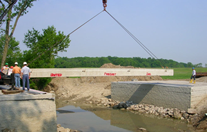
e Federal Highway Administration has built large fortress abutments and piers using geotextile reinforcement and masonry concrete block facing, thus refining the GRS bridge abutment technology. Colorado Department of Transportation (CDOT) built the Founders/ Meadow Bridge with large GRS abutments on a major highway near Denver, Colorado. Most recently Defiance County in Iowa has built over 25 GRS abutment bridges, including their initial Bowman Bridge. Other counties are also adopting this technology because cost savings are commonly over 25 to 40 percent compared to conventional bridge abutment construction.
Their construction methodology is quite simple. A suitable foundation is developed and then the modular concrete block wall facing units are put into place and carefully levelled. Well-graded granular material is backfilled behind the blocks and compacted. Then a geosynthetic reinforcement layer is placed across the blocks and backfill. Then the sequence is repeated over and over on 20 cm (8 inch)(block height) intervals until the desired abutment height is reached. Finally the bridge beams or girders are placed upon the GRS abutment. The GRS-IBS (Geosynthetic Reinforced Soil-Integrated Bridge System) technology is part of a current FHWA “Every Day Counts” initiative to promote this concept and accelerate its adoption.
Conclusions
The use of Geosynthetic-Reinforced Soil (GRS) systems for bridge abutments and piers is receiving considerable interest today because they can offer a relatively inexpensive, quick, and practical solution for bridge foundations in a wide range of applications, particularly for small, simple span bridges up to 40 meters (140 feet) long. This design also minimizes differential settlement and the infamous “bridge bump.” Performance monitoring of these structures has demonstrated that GRS bridge abutment technology can be a “faster, better, cheaper” alternative in many cases to traditional bridge foundations. The recent Federal Highway Administration publication "Geosynthetic Reinforced Soil Integrated Bridge System Synthesis Report" thoroughly documents the current design methodology used for this GRS technology. It is available on-line at:
http://www.fhwa.dot.gov/publications/research/infrastructure/structures/11027/index.cfm
SEE ALSO: Part 1 of this article
Gordon Keller, P.E., has worked since 1972 for the US Forest Service and has played a key role in numerous international training courses, engineering evaluation missions, and conferences. He’s co-led workshops in the Sudan, conducted rural road and environmental analysis throughout Latin America, and worked with the World Bank, the Pan-American Highway Institute, the Rainforest Alliance, and many other organizations. He has also worked closely with the International Road Federation (IRF), a non-governmental, not-for-profit organization dedicated to promoting the development and maintenance of better, safer and more sustainable roads and road networks.


